CSR COMPACT NON-FUSED INTERLOCKED ARKTITE RECEPTACLE - 30 & 60 AMP IF 1439
advertisement

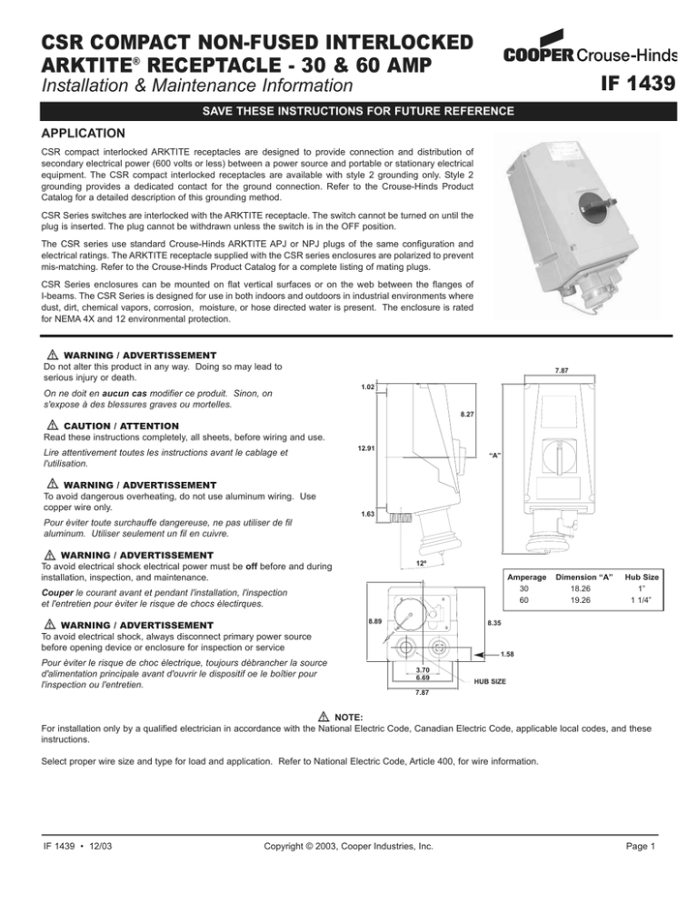
CSR COMPACT NON-FUSED INTERLOCKED ARKTITE® RECEPTACLE - 30 & 60 AMP IF 1439 Installation & Maintenance Information SAVE THESE INSTRUCTIONS FOR FUTURE REFERENCE APPLICATION CSR compact interlocked ARKTITE receptacles are designed to provide connection and distribution of secondary electrical power (600 volts or less) between a power source and portable or stationary electrical equipment. The CSR compact interlocked receptacles are available with style 2 grounding only. Style 2 grounding provides a dedicated contact for the ground connection. Refer to the Crouse-Hinds Product Catalog for a detailed description of this grounding method. CSR Series switches are interlocked with the ARKTITE receptacle. The switch cannot be turned on until the plug is inserted. The plug cannot be withdrawn unless the switch is in the OFF position. The CSR series use standard Crouse-Hinds ARKTITE APJ or NPJ plugs of the same configuration and electrical ratings. The ARKTITE receptacle supplied with the CSR series enclosures are polarized to prevent mis-matching. Refer to the Crouse-Hinds Product Catalog for a complete listing of mating plugs. CSR Series enclosures can be mounted on flat vertical surfaces or on the web between the flanges of I-beams. The CSR Series is designed for use in both indoors and outdoors in industrial environments where dust, dirt, chemical vapors, corrosion, moisture, or hose directed water is present. The enclosure is rated for NEMA 4X and 12 environmental protection. WARNING / ADVERTISSEMENT Do not alter this product in any way. Doing so may lead to serious injury or death. On ne doit en aucun cas modifier ce produit. Sinon, on s'expose à des blessures graves ou mortelles. 7.87 1.02 8.27 CAUTION / ATTENTION Read these instructions completely, all sheets, before wiring and use. Lire attentivement toutes les instructions avant le cablage et l'utilisation. WARNING / ADVERTISSEMENT To avoid dangerous overheating, do not use aluminum wiring. Use copper wire only. Pour èviter toute surchauffe dangereuse, ne pas utiliser de fil aluminum. Utiliser seulement un fil en cuivre. 12.91 “A” 1.63 WARNING / ADVERTISSEMENT To avoid electrical shock electrical power must be off before and during installation, inspection, and maintenance. 12º Amperage 30 60 Couper le courant avant et pendant l'installation, l'inspection et l'entretien pour èviter le risque de chocs èlectirques. WARNING / ADVERTISSEMENT To avoid electrical shock, always disconnect primary power source before opening device or enclosure for inspection or service Pour èviter le risque de choc èlectrique, toujours dèbrancher la source d'alimentation principale avant d'ouvrir le dispositif oe le boîtier pour l'inspection ou l'entretien. 8.89 Dimension “A” 18.26 19.26 Hub Size 1” 1 1/4” 8.35 1.58 3.70 6.69 HUB SIZE 7.87 NOTE: For installation only by a qualified electrician in accordance with the National Electric Code, Canadian Electric Code, applicable local codes, and these instructions. Select proper wire size and type for load and application. Refer to National Electric Code, Article 400, for wire information. IF 1439 • 12/03 Copyright © 2003, Cooper Industries, Inc. Page 1 TABLE 2 RECEPTACLE INSTALLATION: NOTE The CSR Series enclosure should be installed, inspected, operated, and maintained by qualified and competent personnel. WARNING To avoid electrical shock hazard power must be turned OFF before and during installation and maintenance. Separate overcurrent protection must be provided in accordance with the National Electric Code Article 220, or the Canadian Electrical Code, Section B as appropriate To remove front cover for wiring and mounting, fully loosen screws (do not remove from cover) located in four corners of cover. Pull top cover away from bottom enclosure. To replace cover reverse procedure. Slight wiggle of cover and switch handle may be needed to position cover. Do not force. Switch and cover handle must be in OFF position to replace cover. Do not over torque cover screws. Tighten 22 lb./in. max. (2.5 Nm) The Crouse-Hinds Interlocked Receptacle is supplied with 2 hubs for a bottom feed installation. TABLE 1 Myers Hub Size Hub Cat. # Clearance Hole 30A 1" SSTG3 1.32" - 1.38" 60A 1 1/4" SSTG4 1.67" - 1.75" 1. To install a top-feed hub, use a hole saw to drill the appropriate size hole (as shown in Table 1). Install the hub, orienting the ground screw so it may be easily tightened. 2. Select a mounting location that will provide suitable strength and rigidity to support the enclosure. The Crouse-Hinds enclosure can be mounted in a vertical position with receptacle pointing down or in an overhead horizontal position with receptacle cover facing down. 30A 60A Terminal Switch Term. Block Ground Ground Lug Switch Term. Block Ground Ground Lug Wire Size 14-4 AWG 22-4 AWG 22-4 AWG 14-4 AWG 22-4 AWG 22-4 AWG Torque 18 in. lb. 20 in. lb. 35 in. lb. 18 in. lb. 20 in. lb. 35 in. lb. Note: Factory installed auxiliary contacts are wired normally open. Use terminal block 13 / 14 and a wire size #18-14. Torque screws to 7 lb./in. If a normally closed auxiliary contact is required, please consult factory. 6. Test wiring for correctness with continuity checks, and for unwanted grounds with an insulation resistance tester. 7. Ensure operating handle is in OFF position and place cover over enclosure. 8. Tighten four cover screws to 22 lb./in. (2.5 Nm) OPERATING INSTRUCTIONS: 1. Remove receptacle cover 2. Align keyway on plug sleeve with key in receptacle, and insert plug fully. Tighten the plug clamping ring to the receptacle by sliding the clamping ring over the receptacle neck, then turning the ring clockwise by hand to tighten. 3. Turn the handle to the ON position to energize the circuit. 4. The plug cannot be removed when the handle is in the ON position. Turn the handle OFF. Rotate the plug clamping ring counterclockwise, and slide it over the plug body. Pull the plug from the receptacle. NOTE This unit is designed to prevent operation of the switch until a plug is engaged with the receptacle. To prevent damage to the unit, DO NOT operate the unit without first inserting a compatible plug. Damage to the interlock assembly will result if operating handle on cover is forced to the ON position without a plug inserted. 3. Mounting the enclosure - This enclosure will mount directly to a flat surface with four screws through the openings in the base of the enclosure. 4. Attach the field ground wire to the terminal (See Wiring Diagrams on page 4) on the grounding terminal block. (See Table 2 for wire size information.) CAUTION To avoid fire hazard use copper conductors only with an insulation rating of 75°C minimum. Size conductors for 60°C ampacity. 5. Establish a wiring pattern for your system. Attach the field wiring to terminals labeled L1, L2, L3 as appropriate for the installation. (See Wiring Diagrams on page 4 - See Table 2 for wire size information). Maintain color code consistency per your plant wiring scheme. Select appropriate terminal for phase and neutral conductors. For bottom-feed units, run field wiring under DIN rail and loop up to terminal connections. IF 1439 • 12/03 Copyright © 2003, Cooper Industries, Inc. Page 2 MAINTENANCE: WARNING To avoid electrical shock always disconnect primary power source before opening enclosure for inspection or service 1. Frequent inspection should be made to ensure proper and safe operation. A schedule for maintenance checks should be determined by the environment and frequency of use. It is recommended that an inspeciton of the product should be conducted at least once a year. Crouse-Hinds recommends an Electrical Preventative Maintenance program as described in the National Fire Protection Association Bulletin NFPA 70B. 2. Perform visual, electrical, and mechanical checks on all components on a regular basis. - Visually check for undue heating as evidenced by discoloration of wires or other components, damaged or worn parts, or environmental leakage evidenced by water or corrosion in the interior. - Electrically check to make sure that all connections are clean and tight. - Mechanically check that all parts are properly assembled, the interlock is working and operating mechanisms move freely. CONDUIT & GROUNDING CONNECTION INSTRUCTIONS: BOTTOM ENTRY: A clearance hole is provided in the bottom endwall. A Myers™ 1” or 1 1/4” conduit hub is supplied with the CSR unit. See “Installing Hub” below. TOP ENTRY: Measure 2” from the bottom outside edge of the top endwall and mark a horizontal centerline. Decide if you want the top hub to be placed in the center or off-center, but make sure the vertical centerline is no closer than 2” from either edge. Select a position, mark a cross-hair and drill a clearance hole per Table 1. Install the Myers 1” or 1 1/4” conduit hub. See “Installing Hub” below. Note: The factory drilled hub opening in the bottom endwall must be sealed. Install a Myers “Cap Off”, part number STC-4-CP (order separately). 2” Min. 2” Min. 30A - 1.32”-1.38” Dia. 60A - 1.67”-1.75” Dia. 2” INSTALLING THE HUB Remove the lock nut from the hub. Insert threaded end of hub through hole, making sure the rubber gasket is placed between the hub flange and the outside surface of the enclosure. Attach locking nut from the inside of the enclosure and tighten. See “Grounding the Hub” below. HUB RUBBER GASKET GROUND LUG LOCK NUT GROUNDING THE HUB: A ground wire must be installed connecting the Myers Hubs to the ground system. The locking nut on the Myers Hub has a ground termination lug. Install a #8 green ground wire from the Myers ground lug to a green ground block on the din rail. A green ground wire must also be installed between the two hubs. See wiring diagram on next page. SHORT CIRCUIT PROTECTION ACCORDING TO UL: These units are suitable for use on circuits capable of delivering not more than 10,000 RMS symmetrical amperes at 600VAC maximum. IF 1439 • 12/03 Copyright © 2003, Cooper Industries, Inc. Page 3 WIRING DIAGRAMS: (Without Auxiliary Contact) 30 Amp - 3 Wire, 4 Pole Unfused WIRE BLACK SWITCH T3 L3 5 6 L2 3 4 T2 L11 2 T1 WIRE GND GROUND BLOCKS 2 G G4 G3 G2 G1 6 B FIELD WIRING 12 3 HUB/MTG PLT GRD G1 2 3 HUB TO HUB GRD WIRE HUB LOCKNUT CONT CARR S/A Wiring Notes: Do not block terminal openings used for field wiring. Run ground wire from receptacle to terminal connection G3. Run hub ground wire to terminal connection G1. 60 Amp - 3 Wire, 4 Pole Unfused WIRE BLACK SWITCH L3 5 6 T3 L2 3 4 T2 L11 2 T1 WIRE GND GROUND BLOCKS 2 G G4 G3 G2 G1 FIELD WIRING 6 B 12 3 HUB/MTG PLT GRD G1 2 3 HUB TO HUB GRD WIRE HUB LOCKNUT CONT CARR S/A Wiring Notes: Do not block terminal openings used for field wiring. Run ground wire from receptacle to terminal connection G3. Run hub ground wire to terminal connection G1. All statements, technical information and recommendations contained herein are based on information and tests we believe to be reliable. The accuracy or completeness thereof are not guaranteed. In accordance with Crouse-Hinds "Terms and Conditions of Sale", and since conditions of use are outside our control, the purchaser should determine the suitability of the product for his intended use and assumes all risk and liability whatsoever in connection therewith. Cooper Industries Inc. Crouse-Hinds Division PO Box 4999, Syracuse, New York 13221 • U.S.A. Copyright© 2002, Cooper Industries, Inc. IF 1439 Revision 2 New 12/03 Replaces 11/02


