Aeroquip® Brand
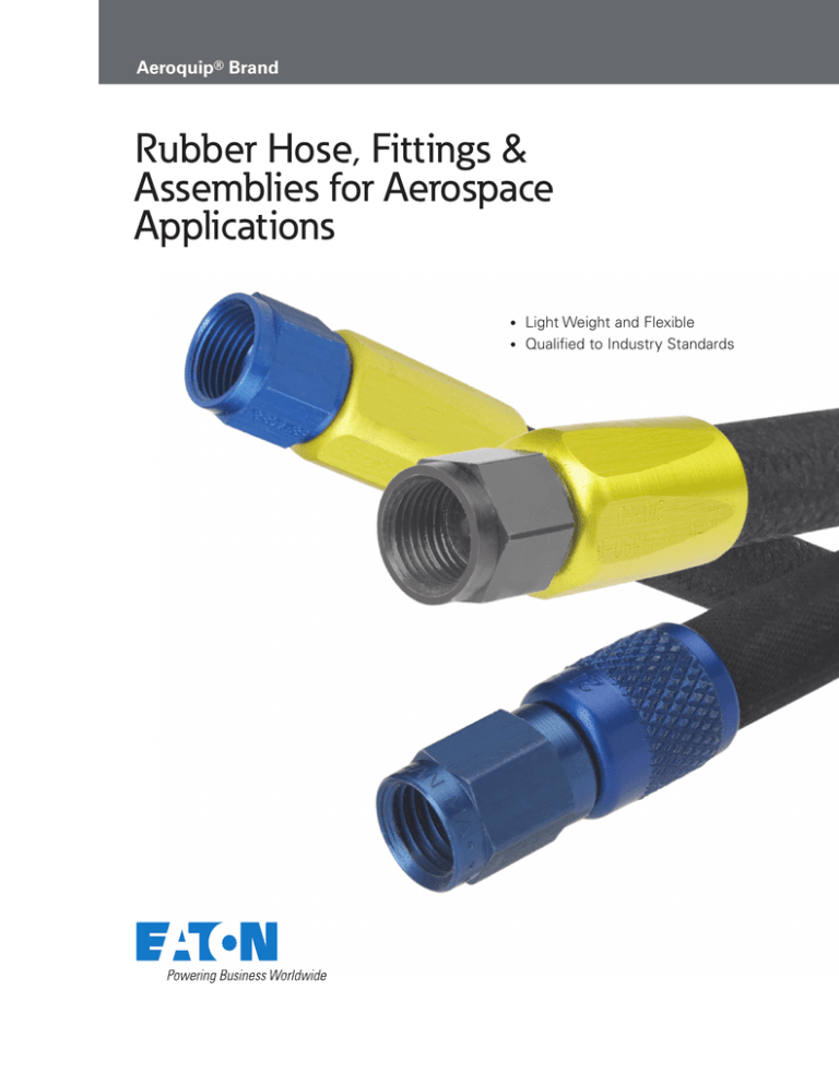
Rubber Hose, Fittings &
Assemblies for Aerospace
Applications
Light Weight and Flexible
• Qualified to Industry Standards
•
Table of Contents
306 Low Pressure Hose, Fittings and Assemblies 1
303, 302A Medium Pressure Hose, Fittings and Assemblies
2
303, 302A Medium Pressure, Flared Hose Assemblies, Sizes -4 through -10
3
303, 302A Medium Pressure, Flared Hose Assemblies, Sizes -12 through -32
3
303, 302A Medium Pressure, Flareless Fittings and Assemblies
4
Aircraft Rubber Hose Assembly Instructions
5
Hose Cut-Off Factors
6
Rubber Hose Assembly Equipment
7
306 Low Pressure Hose, Fittings and Assemblies
Application:
Construction:
•
•
•
Inner Tube: seamless synthetic rubber compound
Reinforcement: single cotton braid
Outer Cover: synthetic rubber cover
Operating Temperatures:
-65° to +160°F
Air or vacuum instrument
systems, automatic pilots and
lines to pressure gauges used
with these systems as specified
in MS33620. Hose assemblies
conform to AN6270. Hose
conforms to MIL- D T L- 5 5 9 3 .
Fittings conform to M I LDTL-38726 and MS27404.*
306 Hose / M I L- D T L- 5 5 9 3
ASSEMBLY SAMPLE PART NUMBER
359 — 4D 0123
Base No.
Size
* Supersedes AN773
Identification:
Black cover with linear yellow
indicator stripe interspersed
with symbol “LP”, hose
manufacturer’s code, size and
date of manufacture (quarter
year/year). Spaced 180° from
this is “Aeroquip 306” in a white
stipe. Markings repeated six
inches apart.
COMPLETE ASSEMBLY
Including 471 Fittings
Weight
Part No. Tube
Size 12” Ass’y (lbs.)
O.D.
359-2DL
AN6270-2-L
1/8
Length in Eights (3/8”)
Length in Inches (12”)
Material Code
HOSE
Part No.
Hose
Size
I.D.
Hose
Size
O.D.
Max.
Oper.
P.S.I.
Min.
Proof
P.S.I.
Min.
Burst
P.S.I.
Min.
Bend
radii
Weight
per inch
(lbs.)
.061
306-2
MIL-DTL-5593-2
.125
.344
300
600
2000
2.00
.004
.188
.406
250
500
1700
2.00
.005
359-3DL
AN6270-3-L
3/16
.080
306-3
MIL-DTL-5593-3
359-4L
AN6270-4-L
1/4
.106
306-4
MIL-DTL-5593-4
.250
.469
200
400
1250
4.00
.006
.375
.594
150
300
1000
4.00
.008
359-6DL
AN6270-6-L
3/8
.145
306-6
MIL-DTL-5593-6
359-8DL
AN6270-8-L
1/2
.236
306-8
MIL-DTL-5593-8
.500
.750
150
250
750
6.00
.012
.292
306-10
MIL-DTL-5593-10
.625
.875
150
250
700
6.00
.014
359-10DL
AN6270-10-L
5/8
Flared AN818 Swivel Nut
• 359 Assembly AN6270
• To mate with MS33656, MS33657, AS4395, AS4396
Material & Finish:
Nut, nipple and socket are
anodized aluminum. All
materials and finishes
conform to applicable
specifications for end fittings
used in aircraft fluid systems.
Length of Assembly
A
HOSE FITTING
Part No.
471-2D
MS27404-2D*
SOCKET
Max.
Dim. Dim. Dim. Weight
A
B
C
(lbs.)
Part
No.
Max.
Dim. Dim.
K
F
NUT
NIPPLE
Max.
Part Min. Part No.
Dim.
Dim.
No. Dim.
M
N
H
C
B
Thread
T
.88
.40
.34
.008
213-2D .531
.453
231-2D
.059
290-2D
.375
.436
5/16 - 24
471/MS27404
Hose Fitting
471-3D
1.00
MS27404-3D*
.44
.32
.012
213-3D .562
.516
231-3D
.122
290-3D
.438
.509
3/8 -24
F
471-4D
1.04
MS27404-4D*
.47
.35
.020
213-4D .625
.578
231-4D
.169
290-4D
.563
.654
7/16 -20
471-6D
1.15
MS27404-6D*
.54
.38
.029
213-6D .650
.703
231-6D
.294
290-6D
.688
.798
9/16 -18
471-8D
1.37
MS27404-8D*
.67
.43
.054
213-8D .800
.891
231-8D
.388
290-8D
.875
1.014
3/4 -16
471-10D
1.57
MS27404-10D*
(K = diameter)
213 Socket
37”
H (I.D.)
.72
.51
.072
213-10D .950
.953 231-10D .481
290-10D
1.000
1.158
7/8 -14
231 Nipple
All dimensions in inches.
* Supersedes AN773.
T
thread
UNF
M hex.
(N = distance across corners)
290/AN818 Nut
EATON Aerospace TF100-16D September 2011
1
303, 302A Medium Pressure Hose, Fittings, and Assemblies
Construction:
Application:
• Inner Tube: seamless synthetic rubber compound
• Reinforcement: synthetic impregnated single-wire braid over single cotton braid
• Outer Cover: synthetic impregnated oil-resistant cotton braid
Medium pressure hydraulic,
pneumatic, fuel, oil and coolant
systems specified in MS33620.
Hose assemblies conform to
MIL-DTL-8795 and MS28741.
Hose conforms to MILDTL-8794. Fittings conform to
MIL-A-5070 and MS24587.*
Hose may be used in
submerged applications.
Operating Temperatures:
Identification:
Grey-black braided cover with
linear yellow marking consisting
of — “M I L-DT L-8 794 ,size,
date of manufacture (quarter
year/year) and hose
manufacturer’s code.” Spaced
90° from this is a yellow
indicator stripe interspersed
with “Aeroquip 303” or
“Aeroquip 302A.” Markings
repeated nine inches apart.
3/16
.175
1/4
.228
5/16
.279
3/8
.391
1/2
.417
5/8
.580
3/4
.750
1
.824
11/4
1.274
11/2
1.558
2
350 — 6 — 0123
Base No.
2.453
HOSE
Part No.
303-3
MIL-DTL-8794-3
303-4
MIL-DTL-8794-4
303-5
MIL-DTL-8794-5
303-6
MIL-D T L-8794-6
303-8
MIL-D T L-8794-8
303-10
MIL-DTL-8794-10
303-12
MIL-DTL-8794-12
302A16
MIL-DTL-8794-16
302A20
MIL-DTL-8794-20
302A24
MIL-DTL-8794-24
302A32
MIL-DTL-8794-32
Hose
Size
I.D.
Hose
Size
O.D.
Max.
Oper.
P.S.I.
Min.
Proof
P.S.I.
.125
.453
3000
6000
12000
3.00
HOSE FITTING
Part No. Max.
Dim. Dim. Dim. Weight
A
B
C
(lbs.)
491-3
*MS24587-3
491-4
*MS24587-4
491-5
*MS24587-5
491-6
*MS24587-6
491-8D
*MS24587-8
491-10D
*MS24587-10
491-12D
*MS24587-12
491-16D
*MS24587-16
491-20D
*MS24587-20
491-24D
*MS24587-24
491-32D
*MS24587-32
1.43
.65
.32
.034
1.51
.65
.35
.055
1.64
.74
.38
.071
1.79
.77
.38
.096
2.22
.94
.43
.097
2.42
1.00
.51
.135
2.70
1.00
.57
.185
2.34
.94
.60
.220
2.48
1.00
.64
.422
2.67
1.09
.74
.504
3.21
1.24
.93
.850
.010
.188
.516
3000
6000
12000
3.00
.011
.250
.578
3000
5000
10000
3.38
.013
.313
.672
2000
4500
9000
4.00
.019
.406
.766
2000
4000
8000
4.62
.022
.922
1750
3500
7000
5.50
.031
.625
1.078
1500
3000
6000
6.50
.038
.875
1.234
800
1600
3200
7.38
.037
1.125
1.500
600
1250
2500
9.00
.043
1.375
1.750
500
1000
2000
11.00
.056
1.812
2.219
350
700
1400
13.25
.078
†† May be used where dynamic impulse does not exceed 3750 psi. If dynamic
impulses of 4500 psi are required MIL-H-8790 hose assemblies shall be used.
Material & Finish:
Nut and nipple, sizes 3 through
6, cadmium-plated steel. Nut and
nipple sizes 8 and up, and
socket, anodized aluminum. All
materials and finishes conform
to applicable specifications for
end fittings used in aircraft fluid
systems.
Length of Assembly
SOCKET
Max.
Part No.
Dim. Dim.
K
F
210-3D
MS24590-3
210-4D
MS24590-4
210-5D
MS24590-5
210-6D
MS24590-6
215-8D
MS24590-8
215-10D
MS24590-10
215-12D
MS24590-12
212-16D
MS24591-16
212-20D
MS24591-20
212-24D
MS24591-24
212-32D
MS24591-32
.1.000
.630
1.100
.693
1.200
.755
1.300
.880
1.650
1.005
1.800
1.234
2.100
1.359
1.661
1.546
1.750
1.921
1.845
2.124
2.250 2.640
NUT
NIPPLE
Max.
Part No. Min. Part No.
Dim.
Dim. Dim.
H
M
N
251-3
MS24588-3
251-4
MS24588-4
251-5
MS24588-5
251-6
MS24588-6
251-8D
MS24588-8
251-10D
MS24588-10
251-12D
MS24588-12
251-16D
MS24589-16
251-20D
MS24589-20
251-24D
MS24589-24
251-32D
MS24589-32
All dimensions in inches.
* Supersedes MS28740, fittings dimensionally and functionally interchangeable.
2
Min.
Min.
Weight
Burst Bend per inch
P.S.I. radii**
(lbs.)
.500
** At maximum operating pressure.
† Not to be used in hydraulic systems.
Flared AN818 Swivel Nut
• 350, 360, 390A Assembly MS28741
• To mate with MS33656, MS33657, AS4395, AS4396
Length in Eights (3/8”)
Length in Inches (12”)
*
* Use D instead of (-) after size for -8 and larger
COMPLETE ASSEMBLY
Including 491 Fittings
Part No.
Weight
Tube
12” Ass’y
Size
(lbs.)
O.D.
350-3-L †
MS28741-3-L
350-4-L ††
MS28741-4-L
350-5-L
MS28741-5-L
350-6-L
MS28741-6-L
360-8-DL
MS28741-8-L
360-10-DL
MS28741-10-L
360-12-DL
MS28741-12-L
390A16DL
MS28741-16-L
390A20DL
MS28741-20-L
390A24DL
MS28741-24-L
390A32DL
MS28741-32-L
ASSEMBLY SAMPLE PART NUMBER
Size
* Supersedes MS28740, fittings
dimensionally and functionally
interchangeable.
• 303 Hose: -65° to +250°F
• 302A Hose: -40° to +250°F
303, 302A/ M I L- D T L- 8 7 9 4 H o se
EATON Aerospace TF100-16D September 2011
Thread
T
.123
290-3
.438
.51
3/8 - 24
.170
290-4
.563
.65
7/16 - 20
.232
290-5
.625
.72
1/2 - 20
.295
290-6
.688
.80
9/16 - 18
.390
290-8D
.875
1.01
3/4 - 16
.484
290-10D
1.000
1.16
7/8 - 14
.608
290-12D
1.250
1.45
11/16 - 12
.810
290-16D
1.500
1.74
1.042
290-20D
2.000
2.33
15/16 12
1.276
290-24D
2.250
2.62
1.745
290-32D
2.875
3.34
Elbow fittings are available for
303, 302A hose.
A
B
C
F
G
hex.
(K = distance across)
491, 451/
MS24587
Hose Fitting
210, 215, 212/
MS24590,
MS24591 Socket
37°
H (I.D.)
251, 271/MS24588,
MS24589 Nipple
15/8 - 12
17/8 - 12
21/2 - 12
M hex.
T
thread
UNF
(N = distance across corners)
290/AN818 Nut
303, 302A Medium Pressure, Flared Hose Assemblies
-4 through -10 and -12 through -32
-4 through -10
Fitting A
Flared AN818 Swivel Nut Fittings and Assemblies
Fitting B
Type
Unsleeved
Firesleeve
Unsleeved
Firesleeve
Unsleeved
Firesleeve
Unsleeved
Firesleeve
Unsleeved
Firesleeve
Unsleeved
Firesleeve
-12 through -32
Fitting A
Alum.
Alum.
Steel
Alum.
Steel
Alum.
Steel
Alum.
Steel
Alum.
Steel
Alum.
Steel
Alum.
Steel
Alum.
Steel
Alum.
Steel
Alum.
Steel
Alum.
Steel
Alum.
Steel
Fitting A
Part No.
491
451
491
491 or 451
491 or 451
491 or 451
491 or 451
491 or 451
491 or 451
491 or 451
491 or 451
491 or 451
491 or 451
980006
980006
980006
980006
980006
980006
980006
980006
980005
980005
980005
980005
Assembly
Base No.
360
390A
350
624000
624000
950012
950012
624040
624040
950004
950004
624023
624023
950010
950816
630907
624071
950003
950668
630908
624055
950002
950680
630909
624036
Fitting B
Part No.
491
451
491
491 or 451
491 or 451
980006
980006
980006
980006
980005
980005
980005
980005
980006
980006
980006
980006
980005
980005
980005
980005
980005
980005
980005
980005
Flared AN818 Swivel Nut Fittings and Assemblies
Fitting B
Type
Unsleeved
Firesleeve
Unsleeved
Firesleeve
Unsleeved
Firesleeve
Unsleeved
Firesleeve
Unsleeved
Firesleeve
Unsleeved
Firesleeve
Material
Material
Alum.
Alum.
Steel
Alum.
Steel
Alum.
Steel
Alum.
Steel
Alum.
Steel
Alum.
Steel
Alum.
Steel
Alum.
Steel
Alum.
Steel
Alum.
Steel
Alum.
Steel
Alum.
Steel
Fitting A
Part No.
91
451
491
491 or 451
491 or 451
491 or 451
491 or 451
491 or 451
491 or 451
491 or 451
491 or 451
491 or 451
491 or 451
980136
980136
980136
980136
980136
980136
980136
980136
980137
980137
980137
980137
Assembly
Base No.
360
390A
350
624000
624000
950234
950234
624037
624037
950192
950192
624066
624066
950247
950817
624089
630910
950233
950818
630911
624912
950248
950819
630905
630913
Fitting B
Part No.
491
451
491
491 or 451
491 or 451
980136
980136
980136
980136
980137
980137
980137
980137
980136
980136
980136
980136
980137
980137
980137
980137
980137
980137
980137
980137
EATON Aerospace TF100-16D September 2011
3
303, 302A Medium Pressure, Flareless Fittings and Assemblies
Globeseal Flareless
Material & Finish:
• 950532 Assembly
• To mate with MS33514, MS33515, AS33514, AS333515
HOSE FITTING
(Globeseal)
Part Max.
Dim. Dim. Weight
No.
A
(lbs.)
B
440-4
440-5
440-6
440-8D
440-10D
Nut and nipple, sizes 4 through
6, cadmium-plated steel. Nut
and nipple sizes 8 and up, and
socket, anodized aluminum. All
materials and finishes conform
to applicable specifications for
end fittings used in aircraft
fluid systems.
Length of Assembly
SOCKET
Part
No.
Dim. Dim.
F
G
Max.
Dim.
K
Part
No.
NIPPLE ASSEMBLY
(Globeseal)
Min.
Max.
Dim.
Dim.
Dim.
M
H
N
Thread
T
7/16 - 20
A
B
.94
.068
210-4D
1.100
.625
.693
440-3-4
.170
.562
.65
1.92
1.05
.081
210-5D
1.200
.688
.755
440-3-5
.232
.625
.72
1/2 - 20
2.11
1.11
.122
210-6D
1.300
.812
.880
440-3-6
.295
.688
.80
9/16 - 18
2.58
1.33
.117
215-8D
1.650
.938
1.005
440-3-8D
.390
.875
1.01
3/4 - 16
2.84
1.46
.167
215-10D 1.800
1.125
1.234
440-3-10D
.484
1.000
1.16
7/8 - 14
215-12D 2.100
1.250
1.359
440-3-12D
.608
1.250
1.45
11/16 - 12
440-3-16D
.810
1.500
1.74
15/16 - 12
210, 215, Socket
T Thread UNJF
Class 38
1.78
440-12D
3.14
1.47
.222
440-16D
2.97
1.60
.286
212-16D 1.661
1.438
1.546
212-20D 1.750
1.750
1.921
440-3-20D
10.42
2.000
2.33
15/8 - 12
212-24D 1.845
1.938
2.124
440-3-24D
1.276
2.250
2.62
17/8 - 12
440-20D
3.17
1.72
.503
440-24D
3.49
1.94
.606
440
Hose Fitting
F
G hex.
(K = distance across corners)
All dimensions in inches.
H (I.D.)
M hex.
(N = distance across corners)
440-3-Size
Nipple Assembly
Globeseal Flareless Assemblies
Fitting A
Fitting B
Type
Unsleeved
Firesleeve
Unsleeved
Firesleeve
Unsleeved
Firesleeve
Unsleeved
Firesleeve
Unsleeved
Firesleeve
Unsleeved
Firesleeve
4
Material
Alum.
Steel
Alum.
Steel
Alum.
Steel
Alum.
Steel
Alum.
Steel
Alum.
Steel
Alum.
Steel
Alum.
Steel
Alum.
Steel
Alum.
Steel
Alum.
Steel
Alum.
Steel
EATON Aerospace TF100-16D September 2011
Fitting A
Part No.
440
440
440
440
440
440
440
440
440
440
980688
980688
980688
980688
980688
980688
980688
980688
980688
980688
980569
980569
980569
980569
Assembly
Base No.
950532
950532
630943
630942
950781
950781
630945
630944
950645
950645
630947
630946
950785
950782
630949
630949
950786
950783
630951
630950
950787
950784
630953
630952
Fitting B
Part No.
440
440
440
440
980688
980688
980688
980688
980569
980569
980569
980569
980688
980688
980688
980688
980569
980569
980569
980569
980569
980569
980569
980569
Aircraft Rubber Hose Assembly Instructions
306, 303 and 302A Hose
Step 1.
Step 2.
Step 4.
Step 5.
Cut hose squarely to length. Use
hose cut-off machine or fine tooth
hacksaw. Do not remove the cover
if using a hacksaw; wrap hose
with several layers of tape before
cutting.
Place socket in vise. Do not overtighten vise on thin walled sockets
of lightweight fittings. Screw hose
counter-clockwise into socket until
it bottoms. Back off 1/4 turn.
Lubricate inside of hose and
nipple threads liberally. Use
lubricating oil, petrolatum or light
grease.
Screw nipple into socket and hose
using wrench on assembly tool
hex. Nut must swivel freely when
assembly tool is removed.
Maximum allowable gap between
nut and socket is 1/16”. On -32
screw in until turning becomes
difficult, back out nipple,
relubricate and reassemble.
Step 3.
Tighten nipple and nut on
assembly mandrel. The use of
Aeroquip brand S1051 hand
assembly tools are recommended
to avoid damage to the sealing
surface and to properly support
the inner tube.
Elbow Hose Assemblies - 303 and 302A
Step 1.
Step 3.
Step 5.
Step 6.
Cut hose squarely to length. Use
hose cut off machine or fine tooth
hacksaw. If using a hacksaw, wrap
hose with tape before cutting. Do
not remove cover.
Flange elbow fittings. Drop flange
over threaded end of nipple. Nipple
shoulder must fit into counter bore
of flange.
Screw nipple into socket and hose
using wrench on elbow hex. Tighten
until hex is snug against socket. On
-32 and larger sizes, screw in until
turning becomes difficult, back out
nipple, relubricate and reassemble.
Adjustments may be necessary to
obtain the desired position angle
between two elbows. In order to
minimize backing off elbows to
position, the following procedure
should supplement Step 5.
Step 2.
Place socket in vises. Do not overtighten vise on thin walled sockets
of light weight fittings. Screw hose
counter-clockwise into socket until it
bottoms. Back off 1/4 turn.
Step 4.
Lubricate inside of hose and nipple
threads liberally. Use lubricating oil,
petrolatum or light grease.
A.Tighten both elbows to maximum allowable gap (reference Step 6C), then start to position for relative angle between the elbows.
B.Finish assembly by adjusting both elbows. Backing-off to position should be avoided and in no case should exceed 1/4 turn.
C.Maximum allowable gap between nipple hex and socket is 1/16” using 303 and 302A hose.
EATON Aerospace TF100-16D September 2011
5
Hose Cut-off Factors
Cut off factors shown below
indicate difference (in inches)
between Length “L” and Length
“J” illustrated on sample hose
assembly.
Length of Hose “J”
Length of Assembly “L”
HOSE DASH SIZE
ASSEMBLY
-2
-3
-4
-5
-6
Flared
Fittings
Straight Swivel to
Straight Swivel
.80
.88
.94
—
Flared
Fittings
Straight Swivel to
Straight Swivel
—
1.32
Globeseal Straight Swivel to
Flareless Straight Swivel
Fittings
—
—
HOSE
Low Pressure
306
Medium Pressure 302A
303
302A
303
6
EATON Aerospace TF100-16D September 2011
-10
-12
-16
-20
-24
-32
1.08
1.34 1.44
—
—
—
—
—
1.30 1.50
1.54
1.90 2.02 2.02 1.90 2.00 2.18
2.50
1.88 2.10
2.22
2.66 2.92 2.94 3.20 3.44 3.88
4.74
-8
Rubber Hose Assembly Equipment
S1385 Hose Cutoff Saw
•
•
•
•
•
•
Low Cost
Compact
Easy Operation
Bench-Mounted
Built-in Safety Features
U.L. Listed
S1380 Hose Assembly
Machine
Machine Specifications
Dimensions: 12” high x 34”
long x 27” wide
Weight: 200 lbs. (approx.)
Hose Range: -3 (3/16”) through
-12 (3/4”), medium pressure -4
(1/4”) through -12 (3/4”), high
pressure
Electrical Requirements
21/2 horsepower electric
motor. 115V, single phase,
AC-DC, 5-60 Hz, 5200 rpm.
Motor Power: 1 horsepower
Eaton’s Aeroquip brand S1385
hose cutoff saw is compact
and easy to operate. The
spring arm is designed with
an improved stabilizer to
insure fast and efficient
cutting of hydraulic hoses. The
S1385 saw will cut single
wire braid hoses through 1.25
inches and 2-wire braid hoses
through 1 inch as well as
textile hoses through 2
inches.
The S1385 cutoff saw is easily
bench-mounted eliminating
the need for a special stand.
It is also equipped with a
safety clutch to prevent motor
damage in case of binding.
The blade is well guarded and
can easily be changed. See
brochure AEB-262 for more
details.
S1385 Features
Electrical Requirements
Eaton designed the S1380 hose
assembly machine to simplify
and speed the assembly of
hoses with standard screw
together reusable fittings.
The machine features a durable
1 H.P., 3-phase, 60 cycle electric
brakemotor operating at 1750
R.P.M. The motor is “C” face
mounted to a speed reducer
which provides a working
spindle with 58.3 R.P.M . With
the S1380 machine you can
quickly assemble straight or
elbow-type reusable fittings on
medium pressure hoses in sizes
-3 (3/16”) through -12 (3/4”) and
high pressure hoses in sizes -4
(1/4”) through -12 (3/4”).
This hose assembly machine is
simple to operate with an easily
adjusted spindle lock for
changing mandrels or
operations and a carriage vise
for accurate fitting assembly.
The complete machine comes
with two sets of chuck jaws,
fire mandrels and operator’s
manual. See brochure AEB-257
for complete information.
230/460V, 3 phase, 60 cycle,
120V
EATON Aerospace TF100-16D September 2011
7
FAILURE OR IMPROPER
SELECTION,USE, OR ASSEMBLY
OF THE PRODUCTS AND
COMPONENTS FOR
APPLICATIONS DESCRIBED
HEREIN CAN RESULT IN
POSSIBLE PROPERTY DAMAGE,
PERSONAL INJURY OR DEATH.
This document and any other
related information from Eaton®
Aeroquip® or its affiliates and
authorized distributors, provide
product options for consideration
by Users having technical
expertise with these products.
Due to the wide variety of
applications and operating
conditions for these products and
components, the User is solely
responsible for making the final
selection of the products and
ensuring that all performance,
safety and warning requirements
for the User's intended application
are met. Eaton® Aeroquip®
recommends that Eaton®
Aeroquip® hose, fittings or
Aeroquip and/or its affiliates
disclaim any obligation or liability
(including all incidental and
consequential damages)to the
extent Eaton® Aeroquip® hose,
fittings or assembly equipment is
used with any other
manufacturer's hose, fittings or
assembly equipment or in the
event that Eaton® Aeroquip®
recommended processes and
product instructions for hose
assemblies are not followed.
The products described herein,
including product features,
specifications, designs, and
availability are subject to change
at any time without notice.
assembly equipment must be
used only with other Eaton®
Aeroquip® hose, fittings or
assembly equipment,and Eaton
8
EATON Aerospace TF100-16D September 2011
Eaton
Aerospace Group
Conveyance Systems Division
300 South East Avenue
Jackson, Michigan 49203-1972
Phone: (517) 787 8121
Fax: (517) 789 2947
Eaton
Aerospace Group
Conveyance Systems Division
90 Clary Connector
Eastanollee, Georgia 30538
Phone: (706) 779 3351
Fax: (706) 779 2638
Eaton
Aerospace Group
Conveyance Systems Division
9650 Jeronimo Road
Irvine, California 92618
Phone: (949) 452 9500
Fax: (949) 452 9992
Eaton
Aerospace Group
Conveyance Systems Division
11642 Old Baltimore Pike
Beltsville, Maryland 20705
Phone: (301) 937 4010
Fax: (301) 937 0134
Eaton
Aerospace Group
Conveyance Systems Division
15 Pioneer Ave.
Warwick, Rhode Island 02888
Phone: (401) 781 4700
Fax: (401) 785 4614
Eaton S. A.
Aerospace Group
Conveyance Systems Division
2 Rue Lavoisier BP 54 78310
Coignieres, France
Phone: (33) 130 69 30 00
Fax: (33) 130 69 30 56
Eaton Limited
Aerospace Group
Conveyance Systems Division
Broad Ground Road
Lakeside, Redditch
Worcestershire
B98 8YS
United Kingdom
Phone: (44) 1527 517555
Fax: (44) 1527 517556
Eaton S.A
Aerospace Group
Conveyance Systems Division
62 Chemin De Pau
64121 Serres-Castet
France
Phone: (33) 559 333 864
Fax: (33) 559 333 865
Eaton Germany GmbH
Aerospace Group
Conveyance Systems Division
Rudolf-Diesel-Str. 8
82205 Gilching
Germany
Phone: (49) 8105 75 0
Fax: (49) 8105 75 55
Vickers Systems Pte Ltd
Aerospace Group
Conveyance Systems Division
Lot 512, Jalan Delima,
Batamindo Industrial Park
Batam 294533, Indonesia
Phone: (62) 770 611823
Fax: (62) 770 611821
Eaton
Aerospace Group
9650 Jeronimo Road
Irvine, California 92618
Phone: (949) 452 9500
Fax: (949) 452 9555
www.eaton.com/aerospace
©2011 Eaton
All Rights Reserved
Printed In USA
Copying or Editing is Forbidden
Form No. TF100-16D
(Supercedes AA129 & AEB261B)
September 2011

