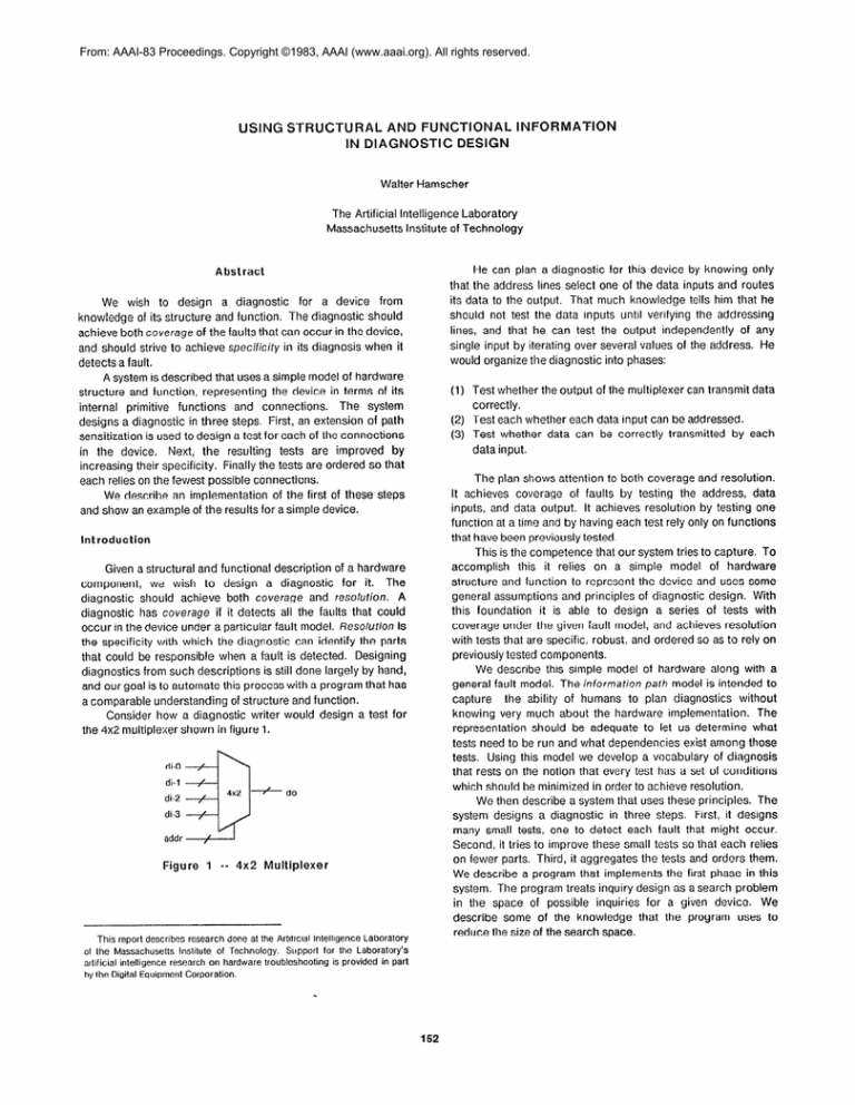
From: AAAI-83 Proceedings. Copyright ©1983, AAAI (www.aaai.org). All rights reserved.
USING
STRUCTURAL
AND FUNCTIONAL
IN DIAGNOSTIC
DESIGN
INFORMATION
Walter Hamscher
The Artificial Intelligence Laboratory
Massachusetts Institute of Technology
He can plan a diagnostic
Abstract
We wish to design a diagnostic
for a device
from
knowledge of its structure and function. The diagnostic should
achieve both coverage of the faults that can occur in the device,
and should strive to achieve specificify in its diagnosis when it
detects a fault.
A system is described that uses a simple model of hardware
structure and function, representing the device in terms of its
internal primitive functions
and connections.
The system
designs a diagnostic in three steps. First, an extension of path
sensitization is used to design a test for each of the connections
in the device.
Next, the resulting tests are improved by
increasing their specificity. Finally the tests are ordered so that
each relies on the fewest possible connections.
We describe an implementation of the first of these steps
and show an example of the results for a simple device.
Introduction
Figure
This report describes
of the Massachusetts
artificial
intelligence
1 -- 4x2
research
Institute
research
by the Digital Equipment
Multiplexer
done at the Artificial
of
rechnology.
on hardware
Corporation.
Intelligence
Support
troubleshooting
Laboratory
for the Laboratory’s
is provided
in part
for this device by knowing
only
that the address lines select one of the data inputs and routes
its data to the output. That much knowledge tells him that he
should not test the data inputs until verifying the addressing
lines, and that he can test the output independently
of any
single input by iterating over several values of the address. He
would organize the diagnostic into phases:
(1) Test whether the output of the multiplexer can transmit data
correctly.
(2) Test each whether each data input can be addressed.
(3) Test whether data can be correctly transmitted by each
data input.
The plan shows attention to both coverage and resolution.
It achieves coverage of faults by testing the address, data
inputs, and data output. It achieves resolution by testing one
function at a time and by having each test rely only on functions
that have been previously tested.
This is the competence that our system tries to capture. To
accomplish
this it relies on a simple model of hardware
structure and function to represent the device and uses some
general assumptions and principles of diagnostic design. With
this foundation
it is able to design a series of tests with
coverage under the given fault model, and achieves resolution
with tests that are specific, robust, and ordered so as to rely on
previously tested components.
We describe this simple model of hardware along with a
path model is intended to
general fault model. The information
capture
the ability of humans to plan diagnostics without
knowing very much about the hardware implementation.
The
representation should be adequate to let us determine what
tests need to be run and what dependencies exist among those
tests. Using this model we develop a vocabulary of diagnosis
that rests on the notion that every test has a set of conditions
which should be minimized in order to achieve resolution.
We then describe a system that uses these principles. The
system designs a diagnostic in three steps. First, it designs
many small tests, one to detect each fault that might occur.
Second, it tries to improve these small tests so that each relies
on fewer parts. Third, it aggregates the tests and orders them.
We describe a program that implements the first phase in this
system. The program treats inquiry design as a search problem
in the space of possible inquiries for a given device. We
describe some of the knowledge that the program uses to
reduce the size of the search space.
Previous
Work in Test Generation
Gate
Until recently,
most efforts
in automated
test generation
Dataln
have focused on gate-level representations
of combinatorial
circuits, and have concentrated on achieving coverage of faults
rather than resolution. The methodology typically employed is
path
sensifization.
Path sensitization
relies on two basic
Selector
concepts:
a fault must be sensitized
and the result must be
propagated
to an output. A fault is sensitized when the effect of
the fault is visible. In the digital domain, if a signal is stuck at
zero (sa-0) and we try to force it to 1, then the fault is sensitized.
to an output of a device by choosing
A result is propagated
inputs of the device so that the presence of the fault can be
determined by looking at the output. The best-known algorithm
for path sensitization is the D-algorithm
([l] and [2]).
Experience with path sensitization indicates that (a) it is
most successful
when gate-level
descriptions
are used,
although this is computationally
expensive; (b) when more
abstract functional descriptions are used, as in [3], a lack of
correspondence
between those functional
descriptions
and
their hardware implementations has a negative effect on both
the coverage and resolution of the resulting test sequences.
Achieving coverage and resolution depends on choosing
an appropriate level of abstraction and viewing the diagnostic
as a collection of primitive tests that can be ordered in such a
way as to increase their resolution.
The key points in our
selection
of a level of abstraction
are the notions that
information
paths
connect
functional
devices,
and that
information flows between these devices along the paths. We
use this model to abstract away from the digital irnplementation
details as much as possible, and yet retain the ability to map the
designed test sequence back onto the real device when the time
comes.
An explanation of how the 4x2 multiplexer works shows
how it can be described in terms of a functional devices: “the
address lines select a data input, that data input goes to the
output; the unselected inputs have no effect on the output.” To
represent these functions, we have chosen three primitive
and the Selector.*
functional devices: the Gate, the Junction,
These are shown in figure 2. The paths that connect these
functional primitives transmit sets of values. Examples of value
Sets are the two-element
sets {h i ,l o}, and the set D =
{dO,dl...dn-I},
where n = 2rk, and k is the width of the path in
bits.
The Gate has a control input with the values nl ana I o.
When the control input is hi, the data input is transmitted to its
output. When the control input is 1o, the output is insensitive to
the data input.
The Junction
has several inputs and a single output; it
merges several information paths.
A Selector has an address input that determines which of
its outputs will have the value hi, while the other outputs will
have the value 1 o.
The multiplexer that we build from these primitives is
shown in figure 3.
2. This set of primitives
No claim to completeness
be expanded.
is a preliminary
is intended,
guess at the set of primitives
and it is expected
DataOut
Junction
Figure
2 -- Primitives
Figure
3 -- Multiplexer
Paths are annotated with several forms of information. The
most important is design information
about the intended
interaction of the devices. These intentions are represented by
matching path input values to path output values. For example,
the multiplexe: is designed so that when a gate’s control is 1 o
its data input will not affect the multiplexer output. We use the
value X-g to represent the value transmitted by the output of a
gate when its control is 1o. and the value X-j on an input of a
junction to represent that the output is insensitive to that input.
The design inforrnation is that X-g and X-j are equivalent.
Henceforth we simply use the value X to represent that value.
Our fault model refers only to path behavior: a fault is
always a fault in the transmission of values from one end of a
path to the other. Restricting faults to appear only on paths
maintains a useful level of generality that encompasses a wide
range of physical faults, including stuck-at and bridging faults.
Our model assumes nonintermittency
and unidirectional
information
ftow on paths3
Faults in devices are not yet
considered; the addition of such failIts will increase the size of
the problem. but we anticipate that it will not significantly
change the design process. At this stage we feel that the path
fault approximation is good enough and general enough that it
is still useful.
We can now interpret the coverage and resolution criteria
described earlier in the light of the intormation path model. A
fundamental concept is that of the inquiry.
An inquiry
is a
needed.
that the set will need to
3. These
sometimes
are common
assumptions
to make when doing
vlolaled in the real world [4].
dtagnosls,
although
question of the form, “Does path X transmit the value Y
correctly?“ The pair (X,Y) is the foclfs of the inquiry. Each
inquiry relies on some subset of paths within the device. Its
on
reliance on those paths is expressed as a set of conditions
those paths. if the inquiry fails, we can conclude that one of the
conditions was violated, but we won’t know which one. Thus,
the larger the set of conditions, the less specific the inquiry.
Each inquiry has a single focus, and consists of a set of input
values
to the device,
a comparison
to be performed
on an
output, and some conditions.
One of the conditions that the
inquiry is obviously testing-- because it was originally postulated
that way-- is that the focus is OK. Other conditions that an
inquiry might include are that all the irnmediate predecessor
paths must be OK.
For example, an inquiry about whether the output of a gate
can transmit the value d2 consists of the input value r!2 on the
data input and h i on the control input, a test to see whcthcr the
output is d2, and the conditions that the data inpM, control
input, and output must all be OK. This simple inquiry is shown
below.
I-l : [ Out ? d2 ]
Inquiry
= d2) (Ctl = hi)
Values:
(DataIn
Conditions:
(ok DataIn)
(ok Ctl)
(Out
‘i‘ 42)
(ok OH!.)
When an inquiry gets a bad result, we sa:; that the inquiry
the paths mentioned in the conditicns.
k fest is
series of inquiries, one for every value of a particular path.4 If
none of the inquiries implicates, then we conclude that the
focus path transmitted all its values correctl;/. In this case we
say that the test exonerates
the path.
A diagnostic may be viewed as an attempt ia exonerate all
the parts in the device under test. Hence a c>r?,gno;iic consists
of an inquiry for every value on every path to see that the path
can transmit the value faithfully; this is hc:;r coverage is
achieved. To provide resolution, each inquiry shou!d implicate
as few paths as possible when it fails.
implicates
Overview
of the Diagnostic
Generation
Pxxedure
Designing a diagnostic is done irl three s::c?ps. First we
create inquiries for every value on every path in the device.
From this step we get a set of inquiries, cash with its own set of
conditions. Second, we analyze and combine the inquiries to
reduce their conditions. This is done using the single point of
hereafter SPFA. In our case, the SPFA is an
failure assumption,
assumption that only a single path is faulty. Third, we collect
the reduced inquiries into tests and order ihe tests in such a
way as to take advantage of prior test results. The resulting
ordered inquiries can then be transMed
into the actual test
patterns using implementation information.
During the Inquiry Design Phase we use an approach
similar to path sensitization, but apply it to our information-path
model of the device.
There are currently 39 rules
that
propagate values and conditions throughout
a device. This
phase will be treated in more depth momentarily.
4. 7 here are 2tk inquiries
restrictive fault model
per path in the the general
there are only O(k).
case, but under a more
The
Inquiry
Improvement
Phase
transforms
each
inquiry to reduce its conditions.
The SPFA can be used to do
this in several ways. One of the techniques used to reduce
conditions is collaboration:
two inquiries about the same focus
can be combined into a compound inquiry having a reduced set
of conditions.
We can do this under the SPFA because only
conditions that appear in both could be responsible for both
inquiries failing. For example, if we have two inquiries for A,
one with the conditions (ok A) and (ok B), the other with the
conditions (ok A) and (ok C ), we can make another inquiry
with only the condition ( ok A).
This phase also collects all the inquiries sharing a focus
path to create a test for that path. For example, the inquiry that
asks whether a gate control input can transmit hi and the
inquiry that asks whether it can transmit 1 o comprise a test for
that path. A test consists of the set of inquiries and a set of
conditions that is the union of the inquiries’ conditions; this
union represents all the paths on which the test relies.
The Test Ordering Phase further improves resolution by
ordering the tests so that each has the minimal set of
conditions.
Tests’ conditions
can be reduced by ordering
because any paths that have already been tested need not
appear in later tests’ conditions. Ordering of tests in this phase
is done pairwise, making use of the principle that “tests that
could implicate fewer paths should be tested first.” For
example, if test T-l has the conditions (ok A) and (ok B) and
test T-2 has the condition (ok A), test T-2 should be done first.
The Inquiry Design Phase
Recall that path sensitization works by sensitizing
a fault
propagating
the result. Henceforth,
we will say that
backward
propagation of values sensitizes a fault, and forward
propagation makes a result visible. To design inquiries, we
propagate
path values and path conditions.
The local
propagations are described by rules.
There are four kinds of rules, capturing four different kinds
of knowledge.
Behavior
rules describe
the input/output
behavior of devices. Sensitization
rules assign values to the
inputs of a device in two situations: (a) when an output of the
device must be forced to some value; (b) when an output of the
device must be made sensitive to one input. Goal rules guide
the direction that the sensitization rules propagate. Condifion
rules add paths to the conditions of the inquiry wherever a fault
might cause the same effect as violating an existing condition.
The rules are associated with devices and propagate across
single devices.
To design an inquiry for a given focus path and value, we
assign the path to have the goal of being sensitized and its
result propagated,
its value to be the focus value, and its
condition to be OK. The rules then propagate goals, values, and
conditions outward to the edges of the device. For some rules
and
choices are available, and we iterate through these. If at any
point we reach a contradictory
assignment of values, we
conclude that the choices we made were incompatible and that
we should go on to the next alternative.
Goal rules tell which direction the sensitization rules will
propagate, but do not assign values to the paths. Each path
value must be either accomplished,
meaning that backward
propagation
must occur from it, or observed,
meaning that
forward propagation must occur. Backward propagation
is
guided by rules that can be expressed as, “if we wish to
accomplish any value on the output, we need to accomplish
some values on the inputs.“ Forward propagation is guided by
rules that are expressed as, “if we wish to observe some input
of a device, then we need to accomplish some values on its
other inputs and observe an output.
Sensitization
rules assign values to inputs of a device in
both forward and backward propagations.
GS-1, shown in
figure 4, is an example of a forward propagation.
To observe
any value on the data input of a Gate, we must assign hi to the
control input, because if we assigned a lo, the output would
always be insensitive to the data input. GS-3, shown in figure 5,
is an example of backward
propagation.
If we want to
accomplish some value di, we need to accomplish that same
value on the data input, and accomplish hi on the control input.
gate to see whether it transmits any value di that is not X, the
control input would be hi and data input di. Since faults on
either the control or data inputs would violate OK on !he output,
OK propagates to both the input paths. Condition rules add to
the conditions of the inquiry wherever a fault might cause the
same effect as violating an already existing condition.
act
hi
Figure
obs
Figure
4 -- Sensitization
5 -- Sensitization
Rule GS- 1
Rule
(or
Behavior rules describe the behavior of the device by
propagating values. For example, a behavior rule for the gate is
that when the control input is hi, the output gets assigned the
value of the data input.
Condition rules propagate conditions after the goals and
values have been assigned. GC-1, in figure 6, is an example of a
backward condition propagation.
To test the data output of a
(ok
GC-1
DI-3)
(ok
(DI-2
(ok DO-l)
DI-2)
(ok
= X)
(ok DO-2)
E-2))
E-3))
This inquiry means: To test whether DO-1 transmits d2,
assign A to be d I, Dl-1 to be d2, and let the other Dl’s be X. The
test will be whether DO has the value d2. If the test succeeds,
conclude that DO-l can transmit d2. If the test fails, conclude
that one of the paths A, E-l, DI-1, DO-l, DO-2, DO-3, or DO was
bad, that E-2 and DI-2 were bad, or that E-3 and DI-3 were bad.
act + obs
ok
E-3
Figure
: [ DO-l ? d2 ]
I-25
(A = dl) (DI-1 = d2)
(DI-3
= X) (DO ? d2)
Conditions:
(ok A) (ok E-l)
(ok DI-1)
(ok DO-3) (ok DO) (or (ok
GS-2
act
ok
Rule
Inquiries
are designed
using these rules.
Consider
designing an inquiry to see whether the output of gate Gl of the
multiplexer transmits the value d2. We start by assigning to the
path the goals act (accomplish) and obs (observe), the value
d2, and the condition OK. Rules fire to propagate
goals,
conditions,
and values throughout
the device;
the final
assignments are shown in figure 7.5 The resulting inquiry is
shown below.
Inquiry
Values:
Figure
6 -- Condition
7 -- Inquiry
155
for
DO-1
Implementation
of the Inquiry
Design Phase
An implementation of the inquiry design phase has been
written in Franz Lisp on a VAX-l l/780 running Unix. Devices
built from the primitives of the information path model are
represented in a language described in [4]. The rules described
above are used to derive the consequences of goal, value, and
condition assignments to paths. Because some rules require
choices to be made, the program designs all the inquiries for a
focus using exhaustive search. This search can be limited by
taking advantage of nonexclusive
sets of choices, and by
making choices that result in locally minimal conditions.
Because of the small size of the multiplexer problem, all the
search trees are of depth 1, there is never more than a single
choice point active at one time, and the greatest number of
inquiries for a single focus is three.6 In general the size of the
search tree has an upper bound of Of(n*m)?hl, where h is the
length of the longest sequence of paths from an input to an
output, n is the number devices in each stage, and m is the
number of possible choices for each device.
When the choices to be made are exclusive, the program
iterates through the possible assignments.
This results in a
depth first search.
In cases where the choices are not exclusive, the program
avoids the iteration-- and thereby some search-- by using a
more efficient
mechanism
that initially
chooses
a// the
alternatives at the choice point. Later assignments may then
simply rule out some of those alternatives without requiring
backing up to the choice point.
Search may also be avoided by making choices that are
hierarchy, we might use this hierarchy as the basis of these
collections; unfortunately
these might not be the appropriate
groupings for solving the problem. The test designer should
derive the same conclusions
as if it had an appropriate
hierarchy
available, thereby
“discovering”
the appropriate
global information.
Building the global information into the
structure description seems like the wrong approach.
However, more important than these shortcomings in the
propagation machinery, the system must also be broadened.
First, it is clear that the vocabulary
of devices is extremely
limited. It must be extended to include computational devices
such as adders and shifters, as well as devices with state.
Second, while path faults is a good place to start on the
problem, the possibility of faults in devices must clearly be
considered.
We anticipate that we will deal with this by the
standard approach of using hierarchic descriptions, and by a
less traditional approach involving the use of a gradation of
condition strengths that will allow us to express minimal device
functionalities.
Acknowledgements
For many helpful discussions, thanks go to all the members
of the Hardware Troubleshooting
group at the MIT Al Lab,
especially Randy Davis, Howard Shrobe, Mark Shirley, Harold
Haig, Steve Polit, and Dan Carnese.
References
[l]
Breuer M, Friedman A, Diagnosis
and Reliable
Systems, Computer Science Press, 1976.
Design
of
likely to yield better inquiries. Since we prefer inquiries with
fewer conditions, we may search the tree in such a way that only
those assignments are tried that keep local conditions to a
minimum.
Digital
Future Directions
[3] Lai, Kwok-Woon, Functional Testing of Digital Systems, PhD
Thesis, Carnegie-Mellon
University, Department of Computer
Science, December 1981, Technical Report CMU-CS-81-148.
All the phases of the diagnostic design procedure have
been implemented and tested on a number of examples. But
there much more to the problem of designing diagnostics, as
suggested
both by the limitations
of the inquiry design
methodology and by the multiplexer problem described earlier.
There are several irnportant limitations to the methodology
of our current system. The rules can only propagate specific
values, when at times sets of values would be more appropriate.
The system also needs nonlocal information about relationships
between values on related paths. In a junction, for example, we
may need to know that to obtain a di at the output, exactly one
of the inputs must be di while the other inputs have X.
Unfortunately
such assertions
about the behavior
of the
junction
cannot be represented
by local assignments
to
individual paths.
One answer to the latter problem is to redefine what things
are local; related paths can be grouped as a collection of paths.
Now any rules that propagate assertions about collections of
paths are in fact local. If the device is described in a structural
5. Around
gates G2 and G3, the conditions
been or’d by a rule that checks whether
the conditions.
on the control and data inputs have
X and
1 o are present and if so “or’s”
6. The outpui path can be tested with the address input assigned dl, d2, or d3.
[2] Roth, John Paul, Computer Logic, Testing, and Verification,
Computer Science Press, 1980, Chapter 3.
[4] Davis R, Shrobe H, Hamscher W, Wieckert K, Shirley M, Polit
S, Diagnosis Based on Description of Structure and Function,
Proc AAAI-82, pp. 137-142.
[5] Hamscher W, R Davis, Using Structural and Functional
Information in Diagnostic Design, MIT Al Memo 707, June 1983.


