Technical Data 4405
Effective October 2015
Supersedes January 2015
C308F
Ferrule and axial lead 3 x 8.4 mm fast-acting, ceramic
tube fuses for barrier applications
Agency information
•
cURus Recognition file number: E19180, Guide
JDYX2/JDYX8
Applications
•
Hazardous environments
•
Oil drilling and refineries
•
Intrinsically safe barriers
Packaging
•
Specify part number and packaging suffix.
•
Package suffixes:
Ferrule
Product description
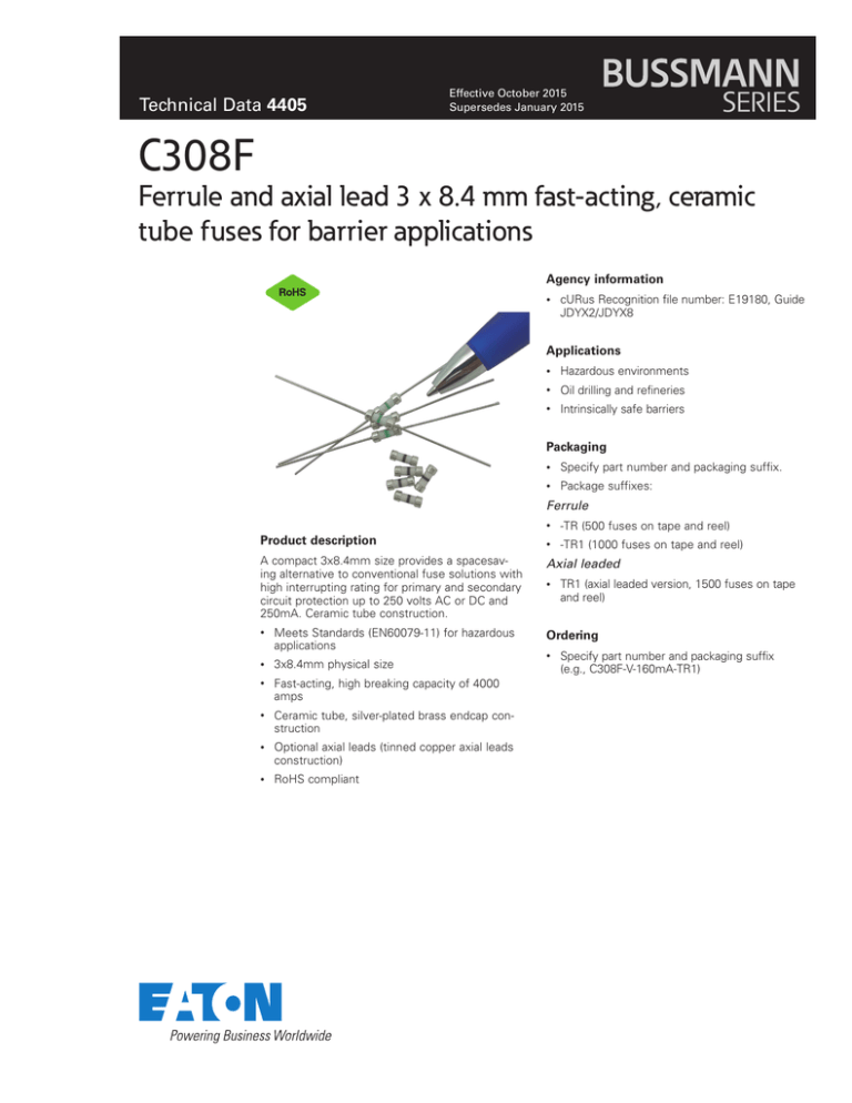
A compact 3x8.4mm size provides a spacesaving alternative to conventional fuse solutions with
high interrupting rating for primary and secondary
circuit protection up to 250 volts AC or DC and
250mA. Ceramic tube construction.
•
Meets Standards (EN60079-11) for hazardous
applications
•
3x8.4mm physical size
•
Fast-acting, high breaking capacity of 4000
amps
•
Ceramic tube, silver-plated brass endcap construction
•
Optional axial leads (tinned copper axial leads
construction)
•
RoHS compliant
•
-TR (500 fuses on tape and reel)
•
-TR1 (1000 fuses on tape and reel)
Axial leaded
•
TR1 (axial leaded version, 1500 fuses on tape
and reel)
Ordering
•
Specify part number and packaging suffix
(e.g., C308F-V-160mA-TR1)
Technical Data 4405
Effective October 2015
C308F
Ferrule and axial lead 3 x 8.4 mm fast-acting, ceramic tube fuses for barrier applications
Product specifications
Part number
Voltage
rating
Vac/dc
Typical DC
cold resistance
(Ω)**
Typical
melting
I²T***
Agency
Information
cURus
Grey
14.2
0.00006
X
Red
9.40
0.00049
X
C308F-V-80mA
Green
5.10
0.00050
X
C308F-V-100mA
Yellow
2.87
0.00087
X
2.20
0.00134
X
Violet
2.05
0.00166
X
Brown
1.01
0.00237
X
0.71
0.00530
X
Color
coding
Ferrule
Axial lead
C308F40mA
C308F-V-40mA
C308F50mA
C308F-V-50mA
C308F80mA
C308F100mA
C308F125mA
C308F-V-125mA
C308F160mA
C308F-V-160mA
C308F200mA
C308F-V-200mA
C308F250mA
C308F-V-250mA
Black
250
Orange
Interrupting
rating @ 250
Vac/dc (amps)*
4000
* AC Interrupting Rating (4000A, PF = 0.4); DC Interrupting Rating measured at rated voltage, time constant 4 microseconds, battery source.
** DC Cold Resistance (Measured at ≤10% of rated current).
***Typical I2t measured at 10In.
Electrical characteristics
Amp Rating
40mA~250mA
% of Amp Rating
Opening Time
110%
4 Hours, min
300%
10 Seconds, max
1000%
0.002 Seconds, max
Environmental data
•
Thermal Shock: MIL-STD-202G, Method 107G (Test Condition 5 cycles -55°C to 125°C)
•
Resistance to Solder Heat: MIL-STD-202G Method 210F
•
Vibration: MIL-STD-202G, Method 201A (10~55Hz) Condition A, “-V” axial leaded version IEC60068-2-6
•
Solderability: J-STD-002C, Test Method C1, “-V” axial leaded version IEC60127-2/A3.3
•
Component Life Reliability: 125°C, 500h
Dimensions–mm
2
www.eaton.com/elx
C308F
Technical Data 4405
Ferrule and axial lead 3 x 8.4 mm fast-acting, ceramic tube fuses for barrier applications
Effective October 2015
Time (s)
Average time-current curves
Current (A)
www.eaton.com/elx
3
C308F
Technical Data 4405
Ferrule and axial lead 3 x 8.4 mm fast-acting, ceramic tube fuses for barrier applications
Effective October 2015
Surface mounting soldering parameters
•
Reflow solder: JEDEC J-STD-202D Tc = 250°C. Tp = 30s
•
Wave and manual solder is not recommended
TP
TC -5°C
tP
Max. Ramp Up Rate = 3°C/s
Max. Ramp Down Rate = 6°C/s
Temperature
TL
Preheat
A
T smax
t
Table 1 - Standard SnPb Solder (Tc)
Package
Thickness
Volume
mm3
<350
Volume
mm3
≥350
<2.5mm)
235°C
220°C
≥2.5mm
220°C
220°C
Table 2 - Lead (Pb) Free Solder (Tc)
Tsmin
25°C
ts
Time 25°C to Peak
Package
Thickness
Volume
mm3
<350
Volume
mm3
350 - 2000
Volume
mm3
>2000
<1.6mm
260°C
260°C
260°C
1.6 – 2.5mm
260°C
250°C
245°C
>2.5mm
250°C
245°C
245°C
Time
Reference JDEC J-STD-020D
Profile Feature
Standard SnPb Solder
Lead (Pb) Free Solder
• Temperature min. (Tsmin)
100°C
150°C
• Temperature max. (Tsmax)
150°C
200°C
• Time (Tsmin to Tsmax) (ts)
60-120 Seconds
60-120 Seconds
Average ramp up rate Tsmax to Tp
3°C/ Second Max.
3°C/ Second Max.
Liquidous temperature (Tl)
Time at liquidous (tL)
183°C
60-150 Seconds
217°C
60-150 Seconds
Peak package body temperature (TP)*
Table 1
Table 2
Time (tp)** within 5 °C of the specified classification temperature (Tc)
20 Seconds**
30 Seconds**
Average ramp-down rate (Tp to Tsmax)
6°C/ Second Max.
6°C/ Second Max.
Time 25°C to Peak Temperature
6 Minutes Max.
8 Minutes Max.
Preheat and Soak
* Tolerance for peak profile temperature (Tp) is defined as a supplier minimum and a user maximum.
** Tolerance for time at peak profile temperature (tp) is defined as a supplier minimum and a user maximum.
4
www.eaton.com/elx
C308F
Technical Data 4405
Effective October 2015
Ferrule and axial lead 3 x 8.4 mm fast-acting, ceramic tube fuses for barrier applications
Through hole wave solder profile
Reflow soldering not recommended
tp
Temperature
Tp
First Wave
Second Wave
Tsmax
Tstyp
Tsmin
Preheat area
Cool down area
Time
Reference EN 61760-1:2006
Profile Feature
Standard SnPb Solder
Lead (Pb) Free Solder
• Temperature min. (Tsmin)
100°C
100°C
• Temperature typ. (Tstyp)
120°C
120°C
• Temperature max. (Tsmax)
130°C
130°C
• Time (Tsmin to Tsmax) (ts)
70 seconds
70 seconds
D preheat to max Temperature
150°C max.
150°C max.
Peak temperature (TP)*
235°C – 260°C
250°C – 260°C
Time at peak temperature (tp)
10 seconds max
5 seconds max each wave
10 seconds max
5 seconds max each wave
Ramp-down rate
~ 2 K/s min
~3.5 K/s typ
~5 K/s max
~ 2 K/s min
~3.5 K/s typ
~5 K/s max
Time 25°C to 25°C
4 minutes
4 minutes
Preheat
Manual solder
350°C, 4-5 seconds. (by soldering iron), generally manual, hand soldering is not recommended.
Life Support Policy: Eaton does not authorize the use of any of its products for use in life support devices or systems without the express written
approval of an officer of the Company. Life support systems are devices which support or sustain life, and whose failure to perform, when properly
used in accordance with instructions for use provided in the labeling, can be reasonably expected to result in significant injury to the user.
Eaton reserves the right, without notice, to change design or construction of any products and to discontinue or limit distribution of any products. Eaton also
reserves the right to change or update, without notice, any technical information contained in this bulletin.
Eaton
Electronics Division
1000 Eaton Boulevard
Cleveland, OH 44122
United States
www.eaton.com/elx
© 2015 Eaton
All Rights Reserved
Printed in USA
Publication No. 4405 — BU-MC15048
October 2015
Eaton is a registered trademark.
All other trademarks are property
of their respective owners.


