Effective April 2016
Supersedes November 2014
Technical Data 4309
CC12H
High I²t Chip fuses
HALOGEN
Pb HF
FREE
Applications
Secondary circuit protection
•
Laptop, notebook, netbook
•
Tablets, e-readers
•
Flat panel displays
•
High definition television (HDTV)
•
LCD/LED backlighting
•
Computers and peripherals
•
Gaming console systems
•
Handheld/portable equipment
•
Mobile device chargers
Automotive
Product description
•
Central body control module
•
Heating ventilation and air conditioning
controllers (HVAC)
•
High I²t
•
Doors, window lift and seat control
•
High inrush withstand capability
•
Digital instrument cluster
•
AEC-Q200 qualified: (750 mA to 20 A)
•
In-vehicle infotainment (IVI) and navigation
•
Excellent temperature and cycling
characteristics
•
Electric pumps, motor control and auxiliaries
•
Powertrain control module (PCU)/Engine
Control unit (ECU)
•
Transmission Control Unit (TCU)
•
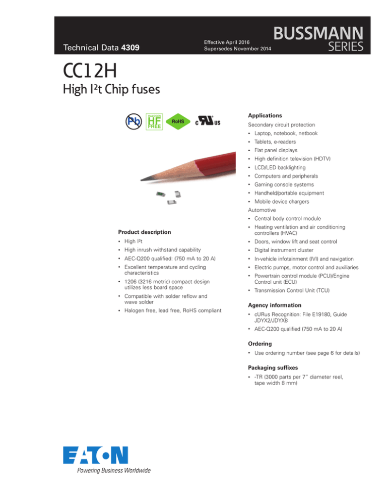
1206 (3216 metric) compact design
utilizes less board space
•
Compatible with solder reflow and
wave solder
•
Halogen free, lead free, RoHS compliant
Agency information
•
cURus Recognition: File E19180, Guide
JDYX2/JDYX8
•
AEC-Q200 qualified (750 mA to 20 A)
Ordering
•
Use ordering number (see page 6 for details)
Packaging suffixes
•
-TR (3000 parts per 7” diameter reel,
tape width 8 mm)
CC12H
High I²t Chip fuses
Technical Data 4309
Effective April 2016
Electrical characteristics
Amp Rating
% of Amp Rating
Opening Time
250 mA – 30 A
100%
4 hours minimum
1A–3A
200%
1.0 s – 60 s
25 A – 30 A
200%
120 s max
1A–5A
250%
5.0 s max
1A–5A
300%
0.1 s – 3.0 s
250 mA – 750 mA
350%
5 s max
6 A – 20 A
350%
5 s max
250 mA – 500 mA
1000%
0.01 ms – 1.0 ms
750 mA – 30 A
1000%
0.2 ms – 20 ms
Product specifications
Current rating
(A)
Voltage rating
(VDC)
Interrupting
rating¹
(A)
Typical DC cold
resistance² (mΩ)
Typical pre-arcing³
I²t (A2s)
Typical voltage
drop (mV)
Part
marking
CC12H250mA
0.25
63
50
3500
0.00038
1400
.25
CC12H375mA
0.375
63
50
1750
0.00077
730
A
CC12H500mA
0.5
63
50
980
0.0019
700
.5
CC12H750mA
0.75
63
50
800
0.15
700
E
CC12H1A
1
63
50
470
0.18
490
H
CC12H1.5A
1.5
63
50
218
0.4
355
K
CC12H2A
2
63
50
133
1.1
305
N
CC12H2.5A
2.5
63
50
79
1.7
240
O
CC12H3A
3
63
50
49
2.2
185
P
CC12H3.5A
3.5
63
50
37
2.7
180
R
CC12H4A
4
63
50
33
3.2
169
S
CC12H4.5A
4.5
32
100
28
4.2
160
X
CC12H5A
5
32
100
23
6
140
T
CC12H6A
6
32
100
15.5
12
150
F
CC12H7A
7
32
100
11.5
18
130
J
CC12H8A
8
32
100
7.3
18
110
V
CC12H10A
10
32
100
6.5
30
90
U
CC12H12A
12
32
100
4.7
45
90
W
CC12H15A
15
32
100
3
33
90
Y
CC12H20A
20
32
100
2
80
90
Q
CC12H25A
25
32
200
3
60
90
L
CC12H30A
30
32
200
2.1
100
90
Z
Part Number
1. DC interrupting rating measured at rated voltage, time constant of less than 50 microseconds, battery source.
2. Typical DC cold resistance measured at <10% of rated current.
3. Typical pre-arcing I²t value is measured at 10In rated current.
2
www.eaton.com/elx
CC12H
High I²t Chip fuses
Technical Data 4309
Effective April 2016
Dimensions–mm
Packaging information- mm
Supplied in tape and reel packaging, 3000 parts per 7” diameter reel.
www.eaton.com/elx
3
CC12H
High I²t Chip fuses
Technical Data 4309
Effective April 2016
I2t vs. time curve
I2t (A2s)
CC12H
Time (s)
4
www.eaton.com/elx
CC12H
High I²t Chip fuses
Technical Data 4309
Effective April 2016
Time (s)
Time vs. current curve
www.eaton.com/elx
5
CC12H
High I²t Chip fuses
Technical Data 4309
Effective April 2016
Temperature derating curve
Environmental data
Operating temperature: -55 °C to +125 °C (with derating); (20 A- 30 A) -40 °C to +85 °C (with derating)
Thermal shock: MIL- STD- 202G, Method 107, (300 cycles -55 °C to +125 °C)
Vibration: MIL-STD- 202G, Method 204, (20 g's for 20 minutes, 12 cycles in each of 3 orientations, 10- 2000 Hz)
Humidity: MIL- STD- 202G, Method 103, (+85 °C, 85% relative humidty, 1000 hours 10% of operating power
Mechanical shock: MIL-STD- 202G, Method 213, Condition C
Ordering codes
The ordering code is the part number replacing the “.” with a “-” plus adding the packaging suffix.
Packaging suffix
• -TR (3000 parts on a 7” reel, tape width 8 mm).
Ordering code
Ordering code
Part Number
-TR option
Part Number
-TR option
CC12H250mA
CC12H250mA-TR
CC12H4A
CC12H4A-TR
CC12H375mA
CC12H375mA-TR
CC12H4.5A
CC12H4-5A-TR
CC12H500mA
CC12H500mA-TR
CC12H5A
CC12H5A-TR
CC12H750mA
CC12H750mA-TR
CC12H6A
CC12H6A-TR
CC12H1A
CC12H1A-TR
CC12H7A
CC12H7A-TR
CC12H1.5A
CC12H1-5A-TR
CC12H8A
CC12H8A-TR
CC12H2A
CC12H2A-TR
CC12H10A
CC12H10A-TR
CC12H2.5A
CC12H2-5A-TR
CC12H12A
CC12H12A-TR
CC12H3A
CC12H3A-TR
CC12H15A
CC12H15A-TR
CC12H3.5A
CC12H3-5A-TR
CC12H20A
CC12H20A-TR
CC12H25A
CC12H25A-TR
CC12H30A
CC12H30A-TR
6
www.eaton.com/elx
CC12H
Technical Data 4309
Effective April 2016
High I²t Chip fuses
Wave solder profile
tp
Temperature
Tp
First Wave
Second Wave
Tsmax
Tstyp
Tsmin
Preheat area
Cool down area
Time
Reference EN 61760-1:2006
Profile Feature
Standard SnPb Solder
Lead (Pb) Free Solder
• Temperature min. (Tsmin)
100°C
100°C
• Temperature typ. (Tstyp)
120°C
120°C
• Temperature max. (Tsmax)
130°C
130°C
• Time (Tsmin to Tsmax) (ts)
70 seconds
70 seconds
D preheat to max Temperature
150°C max.
150°C max.
Peak temperature (TP)*
235°C – 260°C
250°C – 260°C
Time at peak temperature (tp)
10 seconds max
5 seconds max each wave
10 seconds max
5 seconds max each wave
Ramp-down rate
~ 2 K/s min
~3.5 K/s typ
~5 K/s max
~ 2 K/s min
~3.5 K/s typ
~5 K/s max
Time 25°C to 25°C
4 minutes
4 minutes
Preheat
Manual solder
350°C, 4-5 seconds. (by soldering iron), generally manual, hand soldering is not recommended.
www.eaton.com/elx
7
CC12H
High I²t Chip fuses
Technical Data 4309
Effective April 2016
Solder reflow profile
TP
TC -5°C
tP
Max. Ramp Up Rate = 3°C/s
Max. Ramp Down Rate = 6°C/s
Temperature
TL
Preheat
A
T smax
Package
Thickness
Volume
mm3
<350
Volume
mm3
≥350
<2.5mm)
235°C
220°C
≥2.5mm
220°C
220°C
Table 2 - Lead (Pb) Free Solder (Tc)
Tsmin
25°C
t
Table 1 - Standard SnPb Solder (Tc)
ts
Time 25°C to Peak
Package
Thickness
Volume
mm3
<350
Volume
mm3
350 - 2000
Volume
mm3
>2000
<1.6mm
260°C
260°C
260°C
1.6 – 2.5mm
260°C
250°C
245°C
>2.5mm
250°C
245°C
245°C
Time
Reference JDEC J-STD-020D
Profile Feature
Preheat and Soak
Standard SnPb Solder
Lead (Pb) Free Solder
• Temperature min. (Tsmin)
100°C
150°C
• Temperature max. (Tsmax)
150°C
200°C
• Time (Tsmin to Tsmax) (ts)
60-120 Seconds
60-120 Seconds
Average ramp up rate Tsmax to Tp
3°C/ Second Max.
3°C/ Second Max.
Liquidous temperature (Tl)
Time at liquidous (tL)
183°C
60-150 Seconds
217°C
60-150 Seconds
Peak package body temperature (TP)*
Table 1
Table 2
Time (tp)** within 5 °C of the specified classification temperature (Tc)
20 Seconds**
30 Seconds**
Average ramp-down rate (Tp to Tsmax)
6°C/ Second Max.
6°C/ Second Max.
Time 25°C to Peak Temperature
6 Minutes Max.
8 Minutes Max.
* Tolerance for peak profile temperature (Tp) is defined as a supplier minimum and a user maximum.
** Tolerance for time at peak profile temperature (tp) is defined as a supplier minimum and a user maximum.
Life Support Policy: Eaton does not authorize the use of any of its products for use in life support devices or systems without the express written
approval of an officer of the Company. Life support systems are devices which support or sustain life, and whose failure to perform, when properly
used in accordance with instructions for use provided in the labeling, can be reasonably expected to result in significant injury to the user.
Eaton reserves the right, without notice, to change design or construction of any products and to discontinue or limit distribution of any products. Eaton also
reserves the right to change or update, without notice, any technical information contained in this bulletin.
Eaton
Electronics Division
1000 Eaton Boulevard
Cleveland, OH 44122
United States
www.eaton.com/elx
© 2016 Eaton
All Rights Reserved
Printed in USA
Publication No. 4309 BU-MC16040
April 2016
Eaton is a registered trademark.
All other trademarks are property
of their respective owners.


