Effective March 2015
Supersedes April 2014
Technical Data 1170
SurgePODTM
Standard and Universal Surge Protective Device Modules
When a surge condition exceeds either the
Standard or Universal SPD module’s MCOV, the
patented Metal Oxide Varistor (MOV) technology
becomes conductive to safely shunt the surge to
ground.
The same MOV technology also eliminates the
need for additional fusing in UL applications by
safely disconnecting the SPD module upon
reaching an overvoltage breakdown condition.
All Standard or Universal SPD modules are UL
Recognized 1449 3rd Edition for installation in Type
1 or Type 2 surge protective devices.
Optional remote contact signaling is accomplished
with a Normally Open (NO) microswitch that
closes upon the module reaching an overvoltage
breakdown condition.
Optional local visual indication is accomplished
with indicating tabs that protrude through the
device’s top upon the module reaching an
overvoltage breakdown condition.
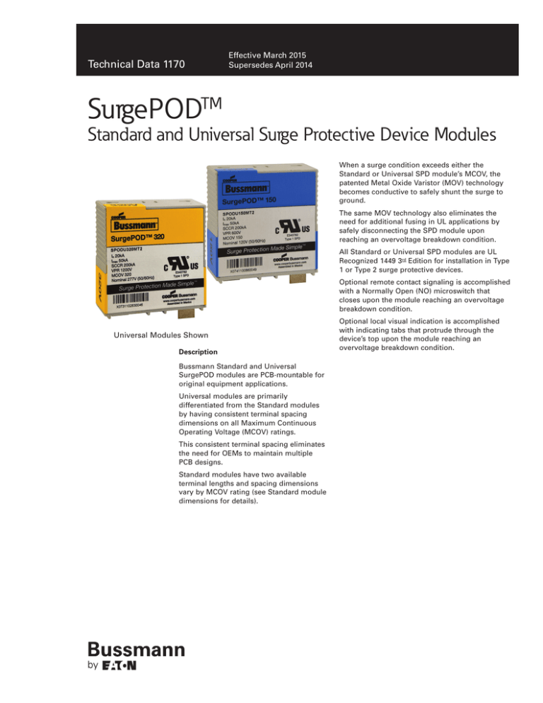
Universal Modules Shown
Description
Bussmann Standard and Universal
SurgePOD modules are PCB-mountable for
original equipment applications.
Universal modules are primarily
differentiated from the Standard modules
by having consistent terminal spacing
dimensions on all Maximum Continuous
Operating Voltage (MCOV) ratings.
This consistent terminal spacing eliminates
the need for OEMs to maintain multiple
PCB designs.
2 color spot version
Standard modules
have two available
Black + PMS 300
terminal lengths and spacing dimensions
vary by MCOV rating (see Standard module
dimensions for details).
Process color version
Black + 100C 44M
One color version
Black
Technical Data 1170
Bussmann SurgePOD
Standard and Universal Modules
Effective March 2015
Optional Local Visual Indication Tabs
Catalog symbols
Standard and Universal modules
•
SPOD (Standard module)
•
SPODU (Universal module)
Ratings
See ratings table
Agency information
•
UL Recognized, 1449 3rd Edition Type 1 Surge Protective Device;
E340782
Flammability rating
•
UL 94V0
Terminal material
•
Nickel-plated copper
Storage and operating temperature range
•
-25°C to +85°C
Traceability
•
SurgePOD device under
normal operation.
Each SurgePOD SPD module is marked with a serial number for
identification and tracking
Options
•
Remote contact signaling is accomplished with a Normally Open
(NO) microswitch that closes upon the module reaching an
overvoltage breakdown condition.
•
Local visual indication is accomplished with indicating tabs that
protrude through the device’s top upon the module reaching an
overvoltage breakdown condition.
Local visual indication
tabs exposed upon
reaching an overvoltage
breakdown condition.
Packaging
•
200 units per master pack
Additional information
•
The SurgePOD module may be damaged by excessive
mechanical shock or rough handling. To ensure integrity of
finished device, do NOT install any SurgePOD module that was
dropped or abused during assembly.
•
Suitability for final application of a SurgePOD module to be
determined by the OEM.
Specifications for SurgePOD Standard and Universal Modules
2
Color Code
Blue
Green
Yellow
Red
Brown
Maximum Continuous Operating Voltage MCOV (Vrms)
150V
270V
320V
420V
550V
Nominal system voltage @ 50/60Hz (Vrms)
120V
220V
277V
347V
480V
Nominal discharge current rating 8/20µs (In)
20kA
20kA
20kA
20kA
20kA
Max discharge current rating 8/20µs (Imax)
50kA
50kA
50kA
50kA
50kA
Short-Circuit Current Rating (SCCR)
200kA
200kA
200kA
200kA
200kA
Voltage Protection Rating (VPR)
600V
900V
1200V
1500V
1500V
www.cooperbussmann.com/surge
Bussmann SurgePOD
Standard and Universal Modules
Technical Data 1170
Effective March 2015
Standard SurgePOD Module Catalog Number System
SPOD
320
Series
MCOV
SPOD = Standard
Terminal
Location
150
270
320
420
550
S
T
R
Optional visual
indicator tab
T = yes
Blank = none
Optional remote
contact signaling
Terminal length
S = short (5.6mm)
L = long (16.8mm)
R = yes (normally open)
Blank = none
Universal SurgePOD Module Catalog Number System
SPODU
320
M
150
270
320
420
550
SPODU = Universal
terminal
location
R
Optional visual
indicator tab
MCOV
Series
T
2
Enclosure Height
2 = tall
Blank = short
T = yes
Blank = none
Optional remote
contact signaling
Terminal length
M = mini (3.4mm)
S = short (5.6mm)
R = yes (normally open)
Blank = none
PCB Layouts
Standard & Universal terminal PCB layout
0.195
[4.9]
0.228
[5.79]
2x ø 0.039
[0.99]
DIM A
0.184
[4.67]
0.050
[1.27]
2X 0.325
8.26
0.231
[5.87]
2X 0.037
0.94
SPOD Standard microswitch terminal PCB layout
1.000
25.40
PCB Layout
0.747
[18.97]
PCB “A” Dimension - in (mm)
SPODU (Universal module)
0.339 (8.61)
SPODU150XXX
0.410 (10.42)
SPOD270XXX
0.377 (9.58)
SPODU270XXX
0.399 (10.14)
SPOD320XXX
0.377 (9.58)
SPODU320XXX
0.399 (10.14)
SPOD420XXX
0.424 (10.77)
SPODU420XXX
0.400 (10.16)
SPOD550XXX
0.425 (10.80)
SPODU550XXX
0.402 (10.21)
0.059
1.50
SPOD150XXX
0.141
3.59
www.cooperbussmann.com/surge
0.199
5.07
Part Number
DIM A
±0.030 (±0.76)
0.231
5.87
Part Number
DIM A
±0.030 (±0.76)
0.448
11.37
0.195
4.95
2X 0.039
0.99
SPOD (Standard module)
SPODU Universal microswitch terminal PCB layout
3
Technical Data 1170
Bussmann SurgePOD
Standard and Universal Modules
Effective March 2015
Standard module dimensions - in [mm]
Universal module dimensions - in [mm]
Tolerance is ± 0.005” [0.13mm] unless otherwise stated.
Tolerance is ± 0.005” [0.13mm] unless otherwise stated.
1.700 0.005
[43.08 0.13]
1.700 0.005
[43.08 0.13]
0.238±0.039
6.04±1.00
0.238±0.039
6.04±1.00
0.957±0.025
24.30±0.64
MIN 0.100
2.54
0.732±0.025
18.60±0.64
0.955±0.025
24.25±0.64
MIN 0.236
6.00
MIN 0.100
[2.54]
MIN 0.236
6.00
0.730±0.025
18.55±0.64
1.684
42.77
*
1.684
42.77
1.728±0.005
43.89±0.13
**
0.135±0.015
3.43±0.38
0.280±0.005
7.11±0.13
0.280±0.005
7.11±0.13
1.280±0.012
32.51±0.30
0.667
16.94
Long
Terminals
0.280
7.11
0.627 .005
[15.93 0.13]
Tall housing shown.
0.512±0.015
13.00±0.38
0.627±0.010
15.92±0.25
0.280
7.11
0.112±0.020
2.84±0.51
DIM "A"
*Short enclosure height
(omits standoffs)
** Tall enclosure height
(includes standoffs)
1.280±0.012
32.51±0.30
0.057±0.025
1.45±0.63
SPODU Universal lead spacing
dimension A
Short
Terminals
0.22±0.05
5.58±1.27
0.280
7.11
Part
Number
0.280
7.11
0.507
12.87
DIM "A"
0.133
3.37
0.068
1.71
“A”
± 0.03 [0.76]
SPODU150XXX
0.410 [10.42]
SPODU270XXX
0.399 (10.14)
SPODU320XXX
0.399.[10.14]
SPODU420XXX
0.400 [10.16]
SPODU550XXX
0.402 [10.21]
SPOD Standard lead spacing
dimension A
Part
Number
“A”
Min
Max
SPOD150XXX
7.08
8.52
SPOD270XXX
8.01
9.51
SPOD320XXX
7.98
9.52
SPOD420XXX
9.25
10.64
SPOD550XXX
9.26
10.72
Eaton’s Bussmann Business
114 Old State Road
Ellisville, MO 63021
United States
www.bussmann.com
© 2015 Eaton
All Rights Reserved
Printed in USA
Publication No. 1170 — BU-SB14228
March 2015
The only controlled copy of this Data Sheet is the electronic read-only version located on the
Bussmann Network Drive. All other copies of this document are by definition uncontrolled.
This bulletin is intended to clearly present comprehensive product data and provide technical
information that will help the end user with design applications. Bussmann reserves the right,
without notice, to change design or construction of any products and to discontinue or limit
distribution of any products. Bussmann also reserves the right to change or update, without
notice, any technical information contained in this bulletin. Once a product has been selected,
it should be tested by the user in all possible applications.
Eaton is a registered trademark.
All other trademarks are property
of their respective owners.


