From: AAAI Technical Report WS-02-18. Compilation copyright © 2002, AAAI (www.aaai.org). All rights reserved.
I Comici Roboti:
Performing the Lazzo of the Statue from the Commedia Dell’Arte
Karl R. Wurst
Department of Computer Science and Engineering, U-155
and
Puppet Arts Program
University of Connecticut, Storrs, CT 06269-3155
Abstract
We are combining robotics and puppetry to build a multirobot team that performs a lazzo from the Commedia
dell’Arte. The robots are built on lego bases using a
Handyboard processor. The robots communicate with each
other and with a human director via radio links. Our robot
hardware and software are described, as our experiences at
AAAI-02.
Why Are We Doing Puppetry?
The University of Connecticut has the only graduatedegree granting Puppet Arts program in the western
hemisphere. (Granting BFA, MA and MFA degrees in
Puppet Arts.) We thought that it would be fun to work
with the Puppet Arts program, and that we might be able
to provide some useful technology to them in return.
Commedia dell’Arte and the Lazzo
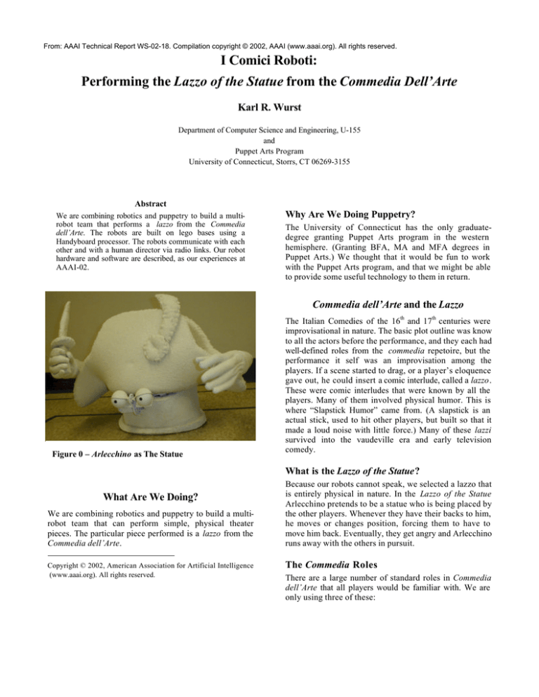
Figure 0 – Arlecchino as The Statue
The Italian Comedies of the 16th and 17th centuries were
improvisational in nature. The basic plot outline was know
to all the actors before the performance, and they each had
well-defined roles from the commedia repetoire, but the
performance it self was an improvisation among the
players. If a scene started to drag, or a player’s eloquence
gave out, he could insert a comic interlude, called a lazzo.
These were comic interludes that were known by all the
players. Many of them involved physical humor. This is
where “Slapstick Humor” came from. (A slapstick is an
actual stick, used to hit other players, but built so that it
made a loud noise with little force.) Many of these lazzi
survived into the vaudeville era and early television
comedy.
What is the Lazzo of the Statue?
What Are We Doing?
We are combining robotics and puppetry to build a multirobot team that can perform simple, physical theater
pieces. The particular piece performed is a lazzo from the
Commedia dell’Arte.
Copyright © 2002, American Association for Artificial Intelligence
(www.aaai.org). All rights reserved.
Because our robots cannot speak, we selected a lazzo that
is entirely physical in nature. In the Lazzo of the Statue
Arlecchino pretends to be a statue who is being placed by
the other players. Whenever they have their backs to him,
he moves or changes position, forcing them to have to
move him back. Eventually, they get angry and Arlecchino
runs away with the others in pursuit.
The Commedia Roles
There are a large number of standard roles in Commedia
dell’Arte that all players would be familiar with. We are
only using three of these:
•
The Statue (Figure 1). Arlecchino (aka
Harlequin) is one of the Zanni, often a trickster.
• The Engineer (Figure 2). Il Dottore is the
pompous academic.
• The Worker (Figure 3). Pedrolino is another of
the Zanni, usually a put-upon servant.
There are many other roles in commedia that we have not
used, such as the miserly Pantalone or the bullying
Captain.
6.
7.
8.
9.
10.
11.
12.
13.
14.
15.
16.
17.
18.
19.
20.
ENGINEER and WORKER: rotate to face plans,
with their backs to the STATUE.
STATUE: rotates to face upstage.
ENGINEER and WORKER: rotate to face
STATUE, express surprise that it has moved.
WORKER: rotates statue to face downstage
again.
WORKER: joins FOREMAN at plans.
FOREMAN and WORKER: rotate to face plans,
with their backs to the STATUE.
STATUE: moves backward out of square.
FOREMAN and WORKER: rotate to face
STATUE, express surprise that it has moved.
WORKER: moves STATUE back into square.
WORKER: joins ENGINEER at plans.
ENGINEER and WORKER: rotate to face plans,
with their backs to the STATUE.
STATUE: rotates to stage right, moves stage
right, rotates downstage again.
ENGINEER and WORKER: rotate to face
STATUE, express surprise that it has moved.
ENGINEER and WORKER: exeunt stage left,
return carrying duct tape and cable ties to secure
STATUE.
STATUE: exit stage right, with ENGINEER and
WORKER chasing.
Figure 2 – Il Dottore as The Engineer
The Theatrical Script
The theatrical script adapted from the Lazzo of the Statue
follows:
Robot Script based on “Lazzo of the Statue”
©2002 Karl R. Wurst
Cast: 3 Robots
• Construction ENGINEER
• Construction WORKER
• STATUE
1.
2.
3.
4.
5.
ENGINEER: enters stage right, pushing an easel
with the plans for the placement of the statue. He
pushes the easel to stage left, leaves it facing
audience at a 45º angle.
ENGINEER: rotates to stage right and begins
directing WORKER to move the statue.
WORKER and STATUE: enter stage right,
WORKER “pushing” STATUE in front of him.
WORKER: continues pushing STATUE to mark
at center stage and rotates STATUE to face
downstage.
WORKER: joins ENGINEER at plans.
Figure 3 – Pedrolino as The Worker
About the Robots
The robots are small, about the size of a 30cm cube,
(Arlecchino is a bit larger.) They have been built out of
available, low-cost components – Lego for the bases to
eliminate machining and a commercially available
processor board, the Handyboard. Most of the custom
work was done on the radio link and the puppet bodies.
Figure 6 - Lego Base Top View
Figure 4 - Lego Base and Handyboard Processor
pulley wheels were substituted.
Lego Bases (Figures 4, 5 & 6)
The bases of the robots are built from Lego Technics. The
drive system is two-motor, diferential steering, with front
and back casters so that the robot can spin on its center.
A Lego frame supports the processor and puppet body.
Two-way Radio Link
Handyboard Processor
Puppet Bodies
The processing is done on a Handyboard running
Interactive C 4.0. This is built on a Motorolla 68HC11
microcontroller running at 8Mhz, and has 32K of RAM.
The bodies of all three robots are build on a construction
hardhat. The inner headband/suspension of the hardhat
has been removed, L-brackets have been attached to hold
the hardhat above the robot base. Two holes have been
made in the sides of the helmets, through which servo
motors have been mounted to operate the arms. The arms
consist of a stiff plastic core, surrounded by foam pipe
insulation, topped with a pair or child-size work gloves
filled with expanded foam. In the case of the Engineer and
Worker robots the only other additions to the hardhat are
the ping pong ball eyes attached to the hat’s visor. The
eyelids on these two robots are currently fixed, but a
mechanism to open and close the eyelids will be added in
the future. The clothing for these two robots consist of
fabric sleeves on the robot arms, and a tube of fabric for
the torso that hangs from the hardhat by Ve lcro.
Additional details such as a platen and collar tabs with
buttons are attached, as is a tie for the Engineer.
The Statue’s hardhat is covered by a bicorn hat made from
reticulated foam (sometimes called “Muppet foam”). After
the hat was shaped and sewn, it was given a number of
coats of liquid neoprene to stiffen it, and provide a surface
suitable for the faux stone surface. The hat was then
primed and sprayed with a commercial faux stone spray.
The arms are of the same construction as the other two
robots, but covered in neoprene and faux stone. The torso
of the Statue is a tube of reticulated foam, given the same
Wheel Encoders
The base was originally built with Lego Rotation Sensors,
which can measure 16 counts per rotation and can
determine direction of rotation. Unfortunately, support for
these sensors was not included in Interactive C 4.0.
Because of this, break-beam sensors and 6-hole Lego
Figure 5 - Lego Base - Bottom View
The robots and PC are linked with a 9600bps radio
connection using the HP series transceivers from Linx.
The transmitter/receiver pair are connected to the
Handyboard’s serial port.
surface treatment as the hat and arms, hung from the
hardhat by Velcro, with a wire frame at the base to help
keep the tube’s shape.
The Statue’s eyes are also mounted on the visor of the
hardhat, but much of the visor has been cut away.
Mounted under the visor is a servomotor to operate the
eyelids (Figure 7). The servomotor had to be mounted
under the visor because the hat blocks access to the
interior of the hardhat. This servomotor will probably be
disguised by a mustache in the future. The eyelids are
Figure 7 – Eye Mechanism
made from the bubble packaging from the ping pong balls,
painted to match the statue, and mounted on a rod that
enters the ping pong balls to provide a pivot point. The
gear mounted on the rod is driven by the gear mounted on
the servomotor to operate the eyelids. This same eyelid
STATUE
/*4*/
{WAITCUE,
mechanism is planned for mounting on the Engineer and
the Worker robots. In this case, however, the servomotor
will be mounted within the hardhat, making it less visible.
About the Software
Each robot is executing its own plan. The robots send
cues back and forth over the radios to keep their plans
synchronized. At the moment, the only radio messages are
these cues , but in the future there will be messages to add,
delete, and modify plan steps.
The implementation of the plans is constrained by the
capabilities of the Handyboard processor and Interactive
C language. The primary limitation imposed by the
Handyboard is the 32K of memory, however this is largely
alleviated by the fact that the Interactive C code is
compiled to a pcode, rather than native machine code.
The primary limitations imposed by the Interactive C
language are the lack of memory allocation and not
allowing pointers to functions. A linked list of plan steps
with pointers to functions in the plan steps would be a
reasonable way to implement the scripts for the robots.
Because these features do not exist, and alternate
implementation was needed.
The plan is represented as an array of plan steps, where
each plan step is a C struct. This struct contains 4 ints:
• Opcode
• Parameter 1
• Parameter 2
• Index of next step
A portion of these plans are shown in Table 1. Editing the
ENGINEER
ENGINEER,0, 1},
{SENDCUE,
{FORWARD,
/*5*/
{SENDCUE,
0,0, 2},
360,0, 3},
{WAITCUE,
{TURN,
WORKER,0, 5},
90,0, 6},
/*6*/
{WAITCUE,
WORKER,0, 7},
0,0, 4},
/*4*/
{SENDCUE,
{MOVEARM,
{MOVEARM,
{WAITCUE,
0,0, 8},
RIGHT,0, 9},
LEFT,0,10},
STATUE,0,11},
/*5*/
{WAITCUE,
{MOVEARM,
{MOVEARM,
{WAITCUE,
STATUE,0,12},
RIGHT,0,13},
LEFT,0,14},
WORKER,0,15},
/*6*/
{WAITCUE,
{TURN,
{FORWARD,
WORKER,0,16},
90,0,17},
144,0,18},
Table 1 – A partial plan.
WORKER
/*4*/
{WAITCUE,
{WAITCUE,
{FORWARD,
/*5*/
{WAITCUE,
{TURN,
{SENDCUE,
{FORWARD,
{TURN,
{PAUSE,
/*6*/
{SENDCUE,
{TURN,
{FORWARD,
{TURN,
ENGINEER,0, 1},
STATUE,0, 2},
360,0, 3},
STATUE,0, 4},
-45,0, 5},
0,0,
101,0,
45,0,
1000,0,
6},
7},
8},
9},
0,0,10},
-45,0,11},
202,0,12},
45,0,13},
plans in this format is difficult, as the plans for the three
robots do not appear side by side as they do in the table.
The numbers in the comments refer to particular panels in
the storyboard of the script, and the blank lines are
needed by the writer to help keep track of the
synchronization between the three robots. A graphical
plan editor would greatly simplify the process of
modifying the existing script and writing new scripts and
is planned, but not yet developed.
The plan interpreter steps through the plan by getting the
opcode of the current plan step from the struct, selecting
the appropriate function to call in a large switch statement,
and passing the two parameters to the function as it is
called. All of the functions have been written to take two
parameters, with one or both of the parameters being
optional. Once the function call is completed, the index of
the next plan step is retrieved from the struct and used to
locate the next plan step.
Routines have been developed to assign space from the
large array that has been allocated to hold the plan steps,
so that it is possible to add steps to the plan. Steps can, of
course, be deleted from the plan simply by changing the
fourth int (the “pointer”) in the struct, but there is
currently no way to reclaim the space to be reused in the
future.
Bumpy Floors
The exhibit hall floors were tile with significant grout lines.
This was not a problem for robots with larger wheels, but
our robots had the problem of the front casters becoming
caught in the grout lines, and snapping off. The Legos
needed to re-engineer this problem were not available.
One other robot team solved this problem by purchasing
vinyl flooring at a home improvement store to provide
their robot with a suitable surface. This may be a solution
that we can use in the future, although we are not sure of
the cost.
Balky Laptop
The laptop we brought along for programming the robots
consistently had problems with crashing an not rebooting.
This also caused significant problems at airport security
when we were asked to turn the laptop on to demonstrate
that it was genuine. Obviously a new laptop is in order.
Burned-out Servomotor
The final problem that caused us to scuttle the demo was
when a servomotor for one of the arms was burned out by
connecting it incorrectly. Extra servos would seem to
something to pack in the future.
Experience at AAAI-02
Our experiences taking the robots to AAAI-02 in
Edmonton, Alberta did not match our expectations very
well.
Radio Noise
The conference facility seemed to very noisy in terms of
radio frequency interference. Undoubtedly some of this
was caused by the large number of robots, but a good deal
of it seemed to be related to the building itself. Our radios
are not very sophisiticated, and could not handle the radio
noise well. Some software redesign was attempted to
handle the problems, with a great deal of help from Randy
Sargent, but this never quite solved the problem. We
briefly worked on developing a workaround for the radio
problem, but abandoned it due to other problems.
The workaround relied on the fact that the radios are
currently used only to transmit synchronization messages
between the robots. Physical switches were attached to
the tops of the robots, so that a human could hit the
switches to relay the synchronization messages. This
might have worked, but it was only bench-tested, not with
the robots on the floor moving around.
Other hardware and software combinations were
suggested by other participants, and these will be
investigated to prevent this problem in the future.
Acknowledgements
We would like to thank (we think…) Holly Yanco for
encouraging us to exhibit our robot team at AAAI-02, and
would like to thank AAAI and NSF for the funding to do
so. Thanks to Randy Sargent for spending a great deal of
time helping us to debug our radio problems. Thanks to
Bartolo Roccoberton of the UConn Puppet Arts program
for the help with the puppetry aspects of the project. And
finally, thanks to Robert McCartney for the help and
encouragement in developing this entire project.
References
Duchartre, P. L., 1966: The Italian Comedy. New York, NY:
Dover Publications.
Gordon, M., 1983: Lazzi: The Comic Routines of the
Commedia dell’Arte. New York, NY: Performing Arts
Journal Publications.
Martin, F. G., 2001: Robotic Explorations: A Hands-On
Introduction to Engineering. Upper Saddle River, NJ:
Prentice-Hall.


