From: AAAI Technical Report WS-02-18. Compilation copyright © 2002, AAAI (www.aaai.org). All rights reserved.
Blue Swarm Sentinel and Blue Swarm 2
Asti Bhatt, Brandon Boldt, Scott Skousen, and Dan Stormont
Utah State University
Department of Electrical and Computer Engineering
4120 Old Main Hill
Logan, Utah 84322-4120
astib@cc.usu.edu, boldt@cc.usu.edu, scskousen@cc.usu.edu, stormontd@acm.org
Abstract
This paper describes the Utah State University (USU) entry
in the 2002 robotic Urban Search and Rescue (USAR)
competition, hosted by the American Association for
Artificial Intelligence (AAAI). More importantly, it also
describes the problems the team encountered in preparing
for this year’s competition, the lessons learned, and plans
for the 2003 USAR competition.
Description of the 2002 Entry
The USU entry for this year’s USAR competition combined
last year’s entry (the Blue Swarm 2) with a coordinator
robot (the Blue Swarm Sentinel). The concept was to have
the Sentinel coordinate with the six robots making up the
Blue Swarm 2 and relay pertinent information (especially the
location of victims) back to a human rescuer viewing a PCbased graphical user interface (GUI) via a radio frequency
(RF) transceiver. The team ran into some problems
implementing this concept, as will be described in the
problems encountered section of this paper. This section
will describe the USU entry as it was intended to operate.
have any way to communicate with rescuers outside of the
arena. To solve this problem, the USU team decided to
build a coordinator robot for the swarm: the Blue Swarm
Sentinel.
Blue Swarm Sentinel
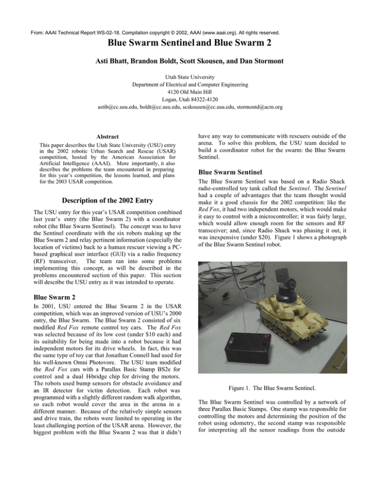
The Blue Swarm Sentinel was based on a Radio Shack
radio-controlled toy tank called the Sentinel. The Sentinel
had a couple of advantages that the team thought would
make it a good chassis for the 2002 competition: like the
Red Fox, it had two independent motors, which would make
it easy to control with a microcontroller; it was fairly large,
which would allow enough room for the sensors and RF
transceiver; and, since Radio Shack was phasing it out, it
was inexpensive (under $20). Figure 1 shows a photograph
of the Blue Swarm Sentinel robot.
Blue Swarm 2
In 2001, USU entered the Blue Swarm 2 in the USAR
competition, which was an improved version of USU’s 2000
entry, the Blue Swarm. The Blue Swarm 2 consisted of six
modified Red Fox remote control toy cars. The Red Fox
was selected because of its low cost (under $10 each) and
its suitability for being made into a robot because it had
independent motors for its drive wheels. In fact, this was
the same type of toy car that Jonathan Connell had used for
his well-known Omni Photovore. The USU team modified
the Red Fox cars with a Parallax Basic Stamp BS2e for
control and a dual H-bridge chip for driving the motors.
The robots used bump sensors for obstacle avoidance and
an IR detector for victim detection. Each robot was
programmed with a slightly different random walk algorithm,
so each robot would cover the area in the arena in a
different manner. Because of the relatively simple sensors
and drive train, the robots were limited to operating in the
least challenging portion of the USAR arena. However, the
biggest problem with the Blue Swarm 2 was that it didn’t
Figure 1. The Blue Swarm Sentinel.
The Blue Swarm Sentinel was controlled by a network of
three Parallax Basic Stamps. One stamp was responsible for
controlling the motors and determining the position of the
robot using odometry, the second stamp was responsible
for interpreting all the sensor readings from the outside
world, and the third stamp was responsible for
communications using the RF transceiver. The motors were
driven by a dual H-bridge chip and the motion of each
motor was measured by counting the number of times a
contact switch with a roller closed as the tank tread passed
under it. This wasn’t the best possible method for
measuring the motion of the treads, but it was the most cost
effective and simplest. In addition to keeping track of the
movement of the treads, a general heading could be
determined from a 3-bit compass module. The Sentinel was
surrounded by six infrared emitter/detector pairs: three
looking forward, one looking to each side, and one looking
backward. It also had an automotive-grade thermopile
sensor looking forward to detect the heat signature from
victims. There was a receiver and a transmitter inside the
chassis that used two whip antennas to communicate with
their matched pairs connected to the rescuer’s PC (the
black box in the photograph is the module that would
attach to the serial port of the PC). The position of the
turret on top of the Sentinel was controlled by a servo
motor, which could turn the turret through a 180° arc from
one side of the robot to the other. On top of the turret was
mounted an X10 wireless color camera that provided an
audio and video feed to the receiver connected to the USB
port of the rescuer’s PC. The block diagram for the Blue
Swarm Sentinel is shown in figure 2.
along with it) either left, right, or back to the forward-facing
home position. The intent was also to have the Blue Swarm
robots follow the Blue Swarm Sentinel when it was ni
manual mode through the use of a beacon on the Sentinel.
Once the rescuer had found an area he wanted the swarm to
explore, he could put the robot into autonomous mode. At
that point, the Blue Swarm Sentinel would attempt to seek
out heat sources in the environment. It would also look for
beacons from the swarm robots indicating that they had
found a victim. In either case, the Sentinel would report the
location of a victim to the GUI to be plotted on the gridbased map the GUI was building while the Sentinel was
exploring. The locations of obstacles would also be
reported and plotted on the map, along with the current
position of the Sentinel. (The positions of the Blue Swarm
2 robots were not plotted by the GUI.) Figure 3 below
shows the GUI used by the human rescuer.
HW Block Diagram
Servo Motor
Encoders
(Futaba FPS3003)
(Radio Shack)
Robot
H Bridge
µcontroller
µcontroller
(TI 1642H5M)
(Basic Stamp A)
(Basic Stamp C)
Motor (2)
µcontroller
(Radio Shack)
(Basic Stamp B)
IR Emitter/
Detector (6)
Temperature
Module
Compass
Module
(Radio Shack)
( Melexis 90601)
( Dinsmore 1525)
Base Station
Receiver
Transmitter
(Ming RE-99)
(Ming TX-99)
Transmitter
Receiver
(Reynolds
TWS 434)
(Reynolds
RWS 434)
Key
Analog signal
Digital signal
RF signal
Sensor
Motor
RF
Computer
Camera &
Microphone
(X-10)
PC
Transmitter
Receiver
(X- 10)
(X- 10)
Figure 3. The human rescuer GUI for the Blue Swarm
Sentinel. The window to the left is the map, with the arrow
indicating the position and heading of the Sentinel. The
manual steering controls, manual/auto button, and turret
controls are all below the map. The window on the right is
the feed from the X10 camera.
Problems Encountered
Figure 2. The block diagram for the Blue Swarm Sentinel.
The software for the Blue Swarm Sentinel had two modes:
manual and autonomous. The human rescuer at the PC
could switch between these modes by pressing a
manual/auto button on the GUI. In manual mode, the
human rescuer could steer the robot by pressing one of
eight direction buttons on the GUI. The robot would then
move one unit (about one foot when going forward or 1.414
feet when moving on a diagonal) and wait for the next
button press. The rescuer would use the video feed from
the robot to steer to a doorway to enter. The rescuer also
had control over the turret in either mode (manual or
automatic) and could pan the turret (and the camera view
The USU team had a number of problems, both in getting
the Blue Swarm Sentinel to work properly and in getting the
coordination with the Blue Swarm 2 to work. In fact, the
team encountered enough problems with the Sentinel
development that the swarm interface was never completed
before the competition. One of the big problems with the
development of the Sentinel was trying to get the three
Basic Stamp s to talk to each other. The approach taken
was to use the Basic Stamp’s capability to perform serial
communications with any of the 16 input/output pins on
the Stamp to set up a ring network between the three
stamps with handshaking provided by signals on additional
I/O pins. Simple tokens and keywords were developed to
simplify the communications and to keep the time
transmitting serially to a minimum. Even so, it was not
uncommon to lose a message between the Stamps. An
even more difficult problem was the RF communications.
The RF modules required a number of unexpected software
kludges, like needing to send dummy messages to wake up
the transmitters prior to sending a real message. In
addition, there were problems on the PC side, where the
circuit the team had built to interface with the PC had to be
replaced when it was unable to communicate with the serial
port on the PC. The RF system also proved to be
unreliable, failing prior to the competition. The RF system
wasn’t the only system to prove unreliable, however. The
sensors also had problems with reliability—especially the
compass sensor. The compass sensor had two problems
actually. One was that the 3-bit module that the team had
been forced to use because of the lack of an analog-todigital (A/D) converter on the Basic Stamp didn’t have
sufficient angular resolution to be able to use it to
accurately turn the robot. Because the compass could only
determine the robot’s heading to somewhere within a 45°
arc, it couldn’t possibly be relied on for anything other than
a rough indication of which of the eight discrete headings
the robot was currently on. The more critical problem was
the compass’ sensitivity to steel and iron in the
environment. It proved to be unusable in most indoor
settings, since the indicated heading would tend to align
with structural elements in the building, regardless of the
actual heading of the robot. This problem would manifest
itself during the competition, along with extreme range
limitations on the RF transceivers that were selected to
replace the failed RF components.
Because of the problems encountered just prior to the
competition, the only viable solution appeared to be to put
together a simpler prototype to try to run in the USAR
competition. A second Sentinel tank was converted for the
contest, using two Basic Stamps mounted on Parallax Board
of Education (BOE) prototyping boards. A simple serial
link was set up between the two boards. One of the BOE
boards was responsible for communications via a Parallax
RF transceiver module, while the second BOE was used to
control the motors and read the inputs from a significantly
smaller suite of sensors. The sensors were a forwardlooking ultrasonic pair for obstacle detection, a thermopile
for victim detection, and a Parallax compass module for
heading determination. Distance traveled was determined
solely by dead reckoning. The camera and the turret were
also abandoned for this robot since the BOE boards didn’t
leave enough room to mount the top shell on the chassis.
While the robot was able to enter a portion of the arena and
was able to detect victims, due to the heavy steel beams in
the roof of the convention center the range of the RF
transceivers was too limited to reach the “safe area” the
human rescuers were required to work in. As mentioned
above, the compass module also failed to give valid
direction readings inside the convention center. Figure 4 is
a block diagram of the prototype robot used in the
competition.
Figure 4. A block diagram of the prototype robot entered
by the USU team in the 2002 USAR competition.
Lessons Learned and Future Work
It is apparent now that the Blue Swarm Sentinel was too
complicated to operate reliably in the USAR environment.
It also relied on sensors (like the compass) and
communications systems (RF transceivers) that proved
unreliable even inside a standing structure—they certainly
wouldn’t be reliable inside a collapsed structure.
Additionally, greater redundancy within the swarm is
needed so the failure of one robot doesn’t incapacitate all
of them.
As a result of these lessons learned, the USU entry in next
year’s USAR competition will based on a larger number of
simpler robots using line of sight communications with at
least two different communications channels to ensure the
map can get out of the USAR arena to the human rescuer.
The underlying idea is to take the first steps toward a truly
portable, disposable swarm that can be quickly deployed at
a disaster site and give first responders a rough idea of
where they should focus their rescue efforts. While next
year’s entry will probably be a subset of the swarm that
would be necessary to provide coverage of the entire arena,
it should serve to validate the viability of this new
approach.
References
Connell, J. “The Omni Photovore: How to Build a Robot
that Thinks like a Roach”, Omni Magazine. October 1988,
pp. 201-212.


