MIT Dept of Mechanical Engineering 2.003 Modeling Dynamics and Control I Spring 2005
advertisement
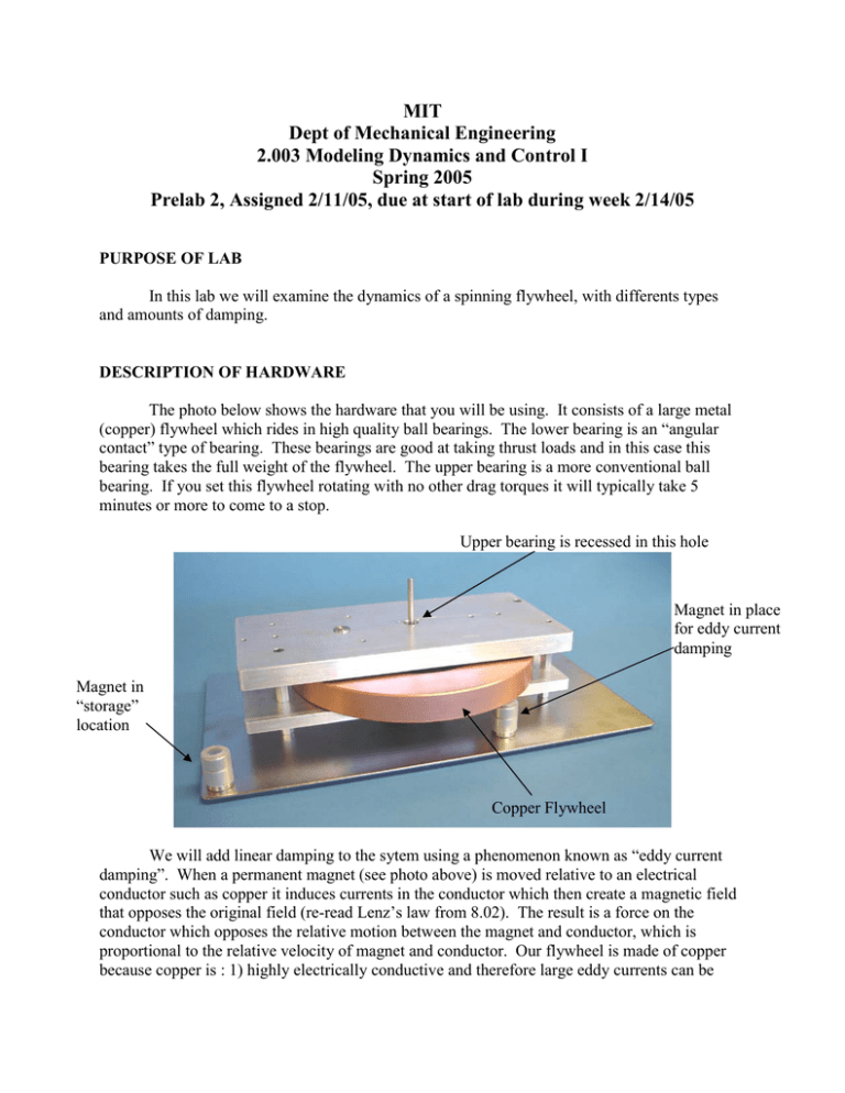
MIT Dept of Mechanical Engineering 2.003 Modeling Dynamics and Control I Spring 2005 Prelab 2, Assigned 2/11/05, due at start of lab during week 2/14/05 PURPOSE OF LAB In this lab we will examine the dynamics of a spinning flywheel, with differents types and amounts of damping. DESCRIPTION OF HARDWARE The photo below shows the hardware that you will be using. It consists of a large metal (copper) flywheel which rides in high quality ball bearings. The lower bearing is an “angular contact” type of bearing. These bearings are good at taking thrust loads and in this case this bearing takes the full weight of the flywheel. The upper bearing is a more conventional ball bearing. If you set this flywheel rotating with no other drag torques it will typically take 5 minutes or more to come to a stop. Upper bearing is recessed in this hole Magnet in place for eddy current damping Magnet in “storage” location Copper Flywheel We will add linear damping to the sytem using a phenomenon known as “eddy current damping”. When a permanent magnet (see photo above) is moved relative to an electrical conductor such as copper it induces currents in the conductor which then create a magnetic field that opposes the original field (re-read Lenz’s law from 8.02). The result is a force on the conductor which opposes the relative motion between the magnet and conductor, which is proportional to the relative velocity of magnet and conductor. Our flywheel is made of copper because copper is : 1) highly electrically conductive and therefore large eddy currents can be induced in it, 2) has a high density – so the flywheel is massive, and 3) is non-magnetic (in a ferromagnetic material such as steel, the magnetic attraction forces would overwhelm the eddy current forces). Under the flywheel and attached to a piece of the flywheel shaft which projects out the bottom, is an “encoder” (see photo below). This is an electronic (actually opto-electronic) device which measures the angular position of the shaft. The selected encoder is a digital device which produces 8192 pulses for each revolution of the shaft. It adds no friction to the system as the optical measurement does not require contact between moving and stationary elements. We connect this digital signal to a box which converts it to an analog signal which respresents angular velocity. We then record this signal on a chart recorder (pen on paper) to have permanent records. Encoder QUESTIONS 1) From the drawing below, ESTIMATE the mass m [kg] and moment of inertia J [kgm2] of the copper flywheel. The density of copper is 8230 Kg/m3. (Note, the dimensions in the drawing are in inches) 2) SKETCH plots of the angular velocity of the flywheel versus time assuming that it is set into motion by hand at an initial angular velocity of w0 and allowed to coast under the following 3 sets of IDEALIZED conditions. Support your sketch in this case with a solution of the appropriate differential equation. a) no friction in the system at all. b) A linear rotational damper (drag torque t = b w) is attached to the shaft of the flywheel. c) The bearings exhibit perfect Coulomb friction (constant drag torque to – not dependent on speed. 3) Assume that the system behavior is dominated by a linear rotational damper (coulomb friction is small). a) Articulate a simple relationship that would have to hold for the statement “the system behavior is dominated by a linear rotational damper (coulomb friction is small)” to be valid. b) Describe two ways that you could measure the damping coefficient, b 4) The graph below shows the decay of a first order system. Estimate the time constant of the system. 6 5 4 3 2 1 0 0 2 4 6 8 10 12 14 16 18 20 Time [sec] 5) The graph below shows a zoomed-in version of the last 14 or 15 seconds of data from the graph in question 4. . Pretend that you didn’t have the graph above and estimate the time constant. Do you expect it to be the same, larger or smaller? Explain. 0.81 1 0.9 0.7 0.9 0.8 0.8 0.6 0.7 0.7 0.5 0.6 0.6 0.4 0.5 0.5 0.4 0.3 0.4 0.3 0.3 0.2 0.2 0.2 0.1 0.1 0.1 00 6 0 0 2 8 2 4 5 106 4 6 12 8 10 10 14 12 1516 14 1618 20 18 20 20 8 10 12 14 16 18 Time [sec] Time [sec] 22 25 20
