M I T
advertisement
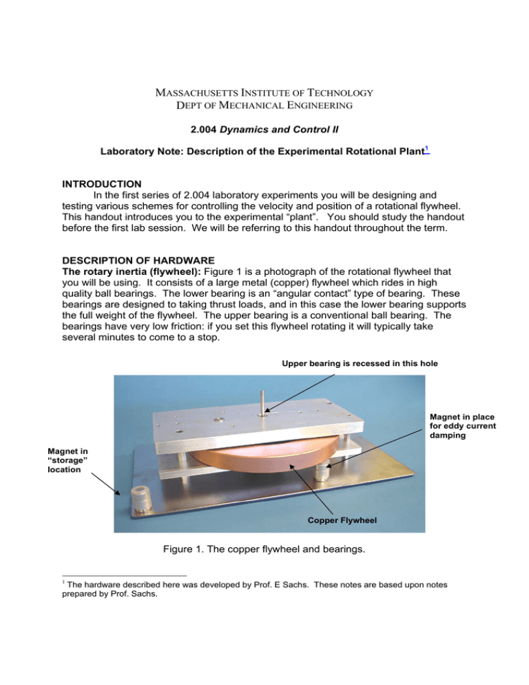
MASSACHUSETTS INSTITUTE OF TECHNOLOGY DEPT OF MECHANICAL ENGINEERING 2.004 Dynamics and Control II Laboratory Note: Description of the Experimental Rotational Plant1 INTRODUCTION In the first series of 2.004 laboratory experiments you will be designing and testing various schemes for controlling the velocity and position of a rotational flywheel. This handout introduces you to the experimental “plant”. You should study the handout before the first lab session. We will be referring to this handout throughout the term. DESCRIPTION OF HARDWARE The rotary inertia (flywheel): Figure 1 is a photograph of the rotational flywheel that you will be using. It consists of a large metal (copper) flywheel which rides in high quality ball bearings. The lower bearing is an “angular contact” type of bearing. These bearings are designed to taking thrust loads, and in this case the lower bearing supports the full weight of the flywheel. The upper bearing is a conventional ball bearing. The bearings have very low friction: if you set this flywheel rotating it will typically take several minutes to come to a stop. Upper bearing is recessed in this hole Magnet in place for eddy current damping Magnet in “storage” location Copper Flywheel Figure 1. The copper flywheel and bearings. The hardware described here was developed by Prof. E Sachs. These notes are based upon notes prepared by Prof. Sachs. 1 In the experiments we will add linear (viscous) damping to the system using a phenomenon knows as “eddy-current damping”. When a permanent magnet (see Fig. 1above) is moved across the surface of an electrical conductor it induces internal currents in the material (eddy currents), which in turn create a magnetic field that opposes the original field (re-read Lenz’s law from 8.02). The result is a force on the magnet proportional to the relative velocity of magnet and metal, in a direction which opposes the motion. It therefore requires work to maintain motion between the magnet and the conductor. Energy is dissipated in the conductor as heat (i2R losses), and the effect is that the eddy-current forces appear as a dissipative frictional force. Our flywheel is made of copper, for several reasons: 1) Copper is highly electrically conductive, and therefore large eddy-currents can be induced in it, 2) Copper is non-magnetic – which is important because ferromagnetic forces would overwhelm the eddy-current forces, and, 3) Copper has a high physical density – with the result that our flywheel is massive (has a large moment of inertia). You will be provided with several magnets, which may be placed under the rim of the flywheel to achieve a range of damping coefficients. The dimensions of the copper flywheel are shown below In Fig. 2. All dimensions are in inches. The density of copper is 8,230 kg/m3. Figure 3. Dimensions of the copper flywheel. Attached to the shaft, under the flywheel, is an optical “rotary encoder,” shown in Fig. 3. This consists of a transparent plastic disk, scribed with 1,024 radial lines. As the disk rotates, these lines interrupt a light beam, and are recorded electronically as a sequence of pulses. Specialized electronics (US Digital ETACH and EDAC2 modules) are used to compute either the angular velocity of the shaft or its angular position. Because there is no mechanical contact, the encoder adds no friction to the system. You will use these signals from these modules in your control system designs. Encoder Figure 2. The rotary encoder for measuring angular velocity and position of the flywheel. The Gear Train: The flywheel will be driven by a dc electric motor through a stepdown gear train, as shown in Fig. 4. A large gear wheel, with 180 teeth, is attached to the flywheel shaft, and is driven by a smaller gear with 44 teeth from the electric motor shaft. Motor drive-shaft with smaller gear (44 teeth) Flywheel drive-shaft with larger gear (180 teeth) Figure 4: Spur gear drive train. The Electric Motor: The system is driven by a permanent magnet dc motor (Maxon 148867). This is a high-quality low-friction 150w, 24 v. dc permanent magnet motor. A specification sheet for the motor is attached. A flexible shaft coupling is used to connect the motor to the drive-shaft to minimize the effects of any shaft misalignment. Electric cable Electric motor Encoder output Flexible coupling Fig. 5 Complete experimental set-up with dc motor. We will be covering the operation of a dc motor in class, but for now we can simply assume that the torque produced by a motor is directly proportional to the current flowing in the windings. Therefore we can define the torque applied to the flywheel by specifying the motor current. The complete rotational set-up is shown in Fig. 5. UPDATED PLANT All the experimental rotational plants were updated in the summer of 2010 to improve the mechanical connection between the flywheel and its drive shaft by adding an aluminum hub on top of the copper flywheel. The updated plant is shown in Fig. 6. This aluminum hub adds about 0.94 lbs of mass to the flywheel, which is not significant compared to the weight of the copper. In addition, the height between the lower and the upper plate was increased to accommodate the added height of the flywheel. Two pieces of plexiglass were also added to the long sides of the upper plate as a safety measure. Fig. 6 Updated plant. MIT OpenCourseWare http://ocw.mit.edu 2.04A Systems and Controls Spring 2013 For information about citing these materials or our Terms of Use, visit: http://ocw.mit.edu/terms.
