Technical Data
Effective January 20, 2015
GDS – Greengate Digital Switch
Catalog#
Prepared by
Project
Date
Comments
Type
Overview
The Digital Switch is available for the Greengate lighting control
panels. It is a decorator style switch with up to six buttons that
offers ON/OFF control of any relay or group of relays in the lighting
control network.
Features
24 VDC supply voltage via the network
Capable of controlling loads over entire lighting network
Integrates with Keeper Enterprise Software or Onboard
programming display
Create custom lighting configurations for each button
Class 2 low voltage wiring
All plastic construction with a separate decorator style snap-on
surround
Suitable for standard single and multi-gang NEMA wall box with
decorator style wallplate
Choice of large or small buttons
A range of seven standard wall station templates can be selected
Tested to withstand 12kV electro-static discharge without damage
of memory loss
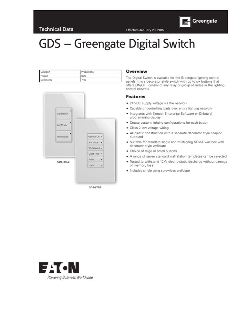
GDS-3TLB
Includes single gang screwless wallplate
GDS-6TSB
Technical Data
GDS – Greengate Digital Switch
January 2015
Specifications
Communications CANbus (GDS-I-KIT is required for GDS integration
on all panels except the CKM)
Size
.75”H x 3.25”W (121mm x 83mm
Description/Operation
The Digital Switch permits multiple control stations to be connected
to the lighting control panels. The control stations provide override
and status feedback. Advanced system features, such as masking
and priorities, are standard on all lighting control panels and can be
applied to these switches to make your application both contractor
and user friendly.
Installation
The Digital Switch fits in a single or multi-gang NEMA wall box and
has a standard decorator style opening to permit single or multi-gang
configurations. The Digital Switches are networked together using
the LCCNP or LCCP wire (ordered separately) and can connect to
the Greengate lighting control panel.
System Schematic
GDS Cable type: Cooper
LCCNP or Cooper LCCP
or Belden 1502, maximum
distance 1000 feet per
GDS network
Zone 1
Zone 2
Zone 3
Zone 4
Zone 1
Zone 2
Zone 3
Zone 4
Zone 5
Zone 5
Zone 6
Zone 6
GDS network uses GDS-I
to access the panel.
Zone 1
GDS network uses GDS-I to access the
panel. GDS-I is integral to the CK4AP
Zone 2
ControlKeeper M
Relay Panel
Power Metering
Zone 1
Zone 2
Zone 3
Zone 5
Zone 5
ControlKeeper T
Relay Panel
Zone 2
Zone 3
Zone 4
Zone 4
Zone 5
Zone 5
Zone 6
Zone 6
Zone 2
Zone 4
Zone 4
Zone 1
Zone 1
Zone 3
Zone 3
Zone 6
Zone 6
Zone 1
Zone 3
Zone 3
CK4AP
Pre-Programmed
Dimming panel
3
4
5
6
7
8
C1
MOV1
C
CAN-TX
C5
LED5
50-022110-01
DIGITA
LED4
U4
U2
PCI-NET
1
U1
MOV3
RSC PIC
C14
U2
+NET-NET
LOAD
LINE
SWIN PIC
RS-232-SP
TB4
RSC STAT
PE-52627
PE-52647
or
Talema
SWV-0-90-330
MOV4
L1
SD1
LED9
LOAD
Gnd
STATUS
1
0 OHM
OPT-47K
RESET PICS
LINE
PCI-NET
TB3
U6
PCI-NET TERM
SWIN STAT
LED8
1
LOCAL
REMOTE
POWER
J7
TB2
J8
ANALOG INPUTS
TB3
ANALOG INPUTS
AN AN AN AN
2 3 4
+24 GND 1
To other lighting control panels
TB4
DIMMING OUTPUTS
DIMMING OUTPUTS
TB5
SWITCH INPUTS
TB6
LSO TEST
SWITCH INPUTS AND LIGHTED SWITCH OUTS
DO RTN DO RTN DO RTN DO RTN IN +24 IN LS IN +24 IN LS
IN
IN LS IN
IN LS
1 1
2 2
3 3
4 4
1
2 1 3
4 2 TP1 5 +24 6 3 7 +24 8 4
To other lighting control panels
Cable type: Belden 9841 or equal
Maximum distance 4000 feet per network
2
ANALOG GND
www.coopercontrol.com
Zone 6
GDS-I-Kit
RS-232
2
LINE
SW2
CAN-RX
Zone 5
TB1
54-022510-
ALL ON
1
Zone 4
50-022510-00
ADDRESS
LED3
PCI 2005 X4 SRC
LED2
LOAD
LED1
NETWORK ALL OFF
TB2
Zone 6
MOV2
Zone 5
LINE
Zone 4
Ethernet link:
Programming access or
Power Metering data access
LiteKeeper
Relay Panel
Zone 2
Zone 2
LOAD
GDS-I
Zone 1
Technical Data
GDS – Greengate Digital Switch
January 2015
Ordering
This is an accessory for Greengate Lighting Control Systems. When
ordering, specify the Digital Switch as a separate system accessory.
GDS - 3TLB - W - S1
Button Engraving
Product
GDS = Greengate Digital Switch
Number of Buttons
1-3 = Large button - TLB
2,4,5,6 = Small button - TSB
Insert Color
W
B
V
G
=
=
=
=
White
Black
Ivory
Gray
Blank
S1
S2
S3
S4
D1
D2
D3
DX
DM
EC1
=
=
=
=
=
=
=
=
=
=
=
Zone 1, Zone 2, Zone 3, etc.
General ON, A/V Mode (2TLB)
General ON, A/V Mode, Whiteboard (3TLB)
General ON, A/V Mode, Quiet (3TLB)
General ON, A/V Mode, Whiteboard, Quiet (4TSB)
General ON, A/V Mode, Raise, Lower (4TSB)
General ON, A/V Mode, Whiteboard, Raise, Lower (5TSB)
ON/OFF, A/V Mode, Whiteboard, Quiet, Raise, Lower (6TSB)
Raise, Lower (2TLB)
ON, OFF, Raise, Lower, Present (5TSB)
General ON, OFF (2TLB)
Additional Options
Catalog #
Description
GDS-I-KIT
Digital Switch Integrator (required per digital switch network connection
on all panels except ControlKeeperM Series and CK4AP)
Communication Cable, 500 ft spool
(See Communication Cable Spec Sheet for more information)
Communication Cable, 500 ft spool, Non-plenum
(See Communication Cable Spec Sheet for more information)
LCCP
LCCNP
NNote: GDS stations with the S1 through EC1 Button Engraving options are also pre-
addressed for easy integration into the CK4AP pre-programmed lighting panel and
other solutions.
NNote: DS stations with the S1 through EC1 Button Engraving are also available with a
“-RM2” suffix for the AP Classroom Two Room Dimming Solution.
Engraving Options
The Digital Switch is available in multiple standard engraved options.
Simply append the station model to the appropriate Digital Switch.
Example Catalog #
Button Qty
Button Color
Engraving
GDS-3TLB-W-S2
GDS-6TSB-B-D3
GDS-5TSB-W
3
6
5
White
Black
White
General On, A/V Mode, Whiteboard
General On, A/V Mode, Whiteboard, Quiet Time, Raise, Lower
Zone 1, Zone 2, Zone 3, Zone 4, Zone 5
General On
General On
General On
A/V Mode
A/V Mode
Whiteboard
Off
Quiet Time
Whiteboard
General On
General On
A/V Mode
A/V Mode
Whiteboard
Whiteboard
Raise
Quiet Time
Lower
Raise
Lower
GDS-3TLB-*-S2
GDS-4TSB-*-S4
GDS-2TLB-*-EC1
GDS-5TSB-*-D2
GDS-6TSB-*-D3
www.coopercontrol.com
3
Technical Data
GDS – Greengate Digital Switch
January 2015
Eaton
1000 Eaton Boulevard
Cleveland, OH 44122
United States
Eaton.com
Eaton’s Cooper Controls Business
203 Cooper Circle
Peachtree City, GA 30269
coopercontrol.com
© 2014 Eaton
All Rights Reserved
Printed in USA
Publication No. ACC141056
January 20, 2015
Eaton is a registered trademark.
All other trademarks are property
of their respective owners.

