Institute of Precision Engineering
MANUAL
SUPERPLASTIC FORMING SIMULATION WITH ABAQUS 6.4-1
Section
HEADING
PART
DEFINITION
(1st method)
(2nd method)
Sample input file *.inp
Commands
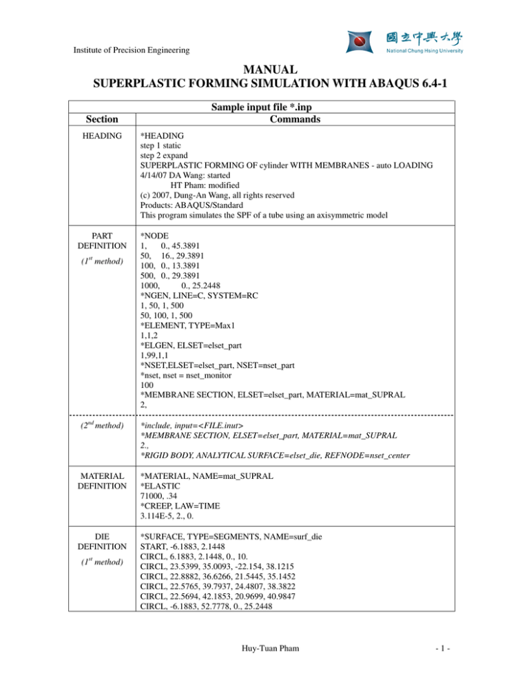
*HEADING
step 1 static
step 2 expand
SUPERPLASTIC FORMING OF cylinder WITH MEMBRANES - auto LOADING
4/14/07 DA Wang: started
HT Pham: modified
(c) 2007, Dung-An Wang, all rights reserved
Products: ABAQUS/Standard
This program simulates the SPF of a tube using an axisymmetric model
*NODE
1,
0., 45.3891
50, 16., 29.3891
100, 0., 13.3891
500, 0., 29.3891
1000,
0., 25.2448
*NGEN, LINE=C, SYSTEM=RC
1, 50, 1, 500
50, 100, 1, 500
*ELEMENT, TYPE=Max1
1,1,2
*ELGEN, ELSET=elset_part
1,99,1,1
*NSET,ELSET=elset_part, NSET=nset_part
*nset, nset = nset_monitor
100
*MEMBRANE SECTION, ELSET=elset_part, MATERIAL=mat_SUPRAL
2,
*include, input=<FILE.inut>
*MEMBRANE SECTION, ELSET=elset_part, MATERIAL=mat_SUPRAL
2.,
*RIGID BODY, ANALYTICAL SURFACE=elset_die, REFNODE=nset_center
MATERIAL
DEFINITION
*MATERIAL, NAME=mat_SUPRAL
*ELASTIC
71000, .34
*CREEP, LAW=TIME
3.114E-5, 2., 0.
DIE
DEFINITION
*SURFACE, TYPE=SEGMENTS, NAME=surf_die
START, -6.1883, 2.1448
CIRCL, 6.1883, 2.1448, 0., 10.
CIRCL, 23.5399, 35.0093, -22.154, 38.1215
CIRCL, 22.8882, 36.6266, 21.5445, 35.1452
CIRCL, 22.5765, 39.7937, 24.4807, 38.3822
CIRCL, 22.5694, 42.1853, 20.9699, 40.9847
CIRCL, -6.1883, 52.7778, 0., 25.2448
(1st method)
Huy-Tuan Pham
-1-
Institute of Precision Engineering
*RIGID BODY, ANALYTICAL SURFACE=surf_die, REFNODE=1000
CONTACT
DEFINITION
*SURFACE, NAME=surf_part, Type=ELEMENT
elset_part,SPOS
*CONTACT PAIR,INTERACTION=contact_part, smooth=0.2
surf_part, surf_die
*SURFACE INTERACTION, NAME=contact_part
***FRICTION
**0.1
BOUNDARY
AND INITIAL
CONDITIONS
*BOUNDARY
1, 1
100, 1
50, 2
1000,1,6
*INITIAL CONDITIONS, TYPE=STRESS, UNBALANCED STRESS=STEP
elset_part, 6.89e-3, 6.89e-3
*AMPLITUDE,DEFINITION=SOLUTION DEPENDENT,NAME=AUTO
1.,0.1,1000.
STEP 1
STATIC
SIMULATION
OUTPUT
*STEP, INC=100000, NLGEOM, unsymm=yes
*STATIC
2.E-3,1.0,1.e-5, 1e-1
*DLOAD
elset_part,P, 1e-3
*monitor, dof=2, node= nset_monitor, frequency=1
*CONTACT PRINT, FREQUENCY=1
*CONTACT FILE, FREQUENCY=1, NSET=nset_part
*EL PRINT, ELSET=elset_part , FREQUENCY=1
S, E
CE,
SINV,
*PRINT, CONTACT=YES
*NODE FILE, NSET=nset_part, FREQUENCY=1
U,
*OUTPUT,FIELD, Frequency=1
*NODE OUTPUT
U,RF
*Element Output
S, E
*END STEP
STEP 2
VISCO
SIMULATION
OUTPUT
*STEP, INC=100000, NLGEOM, unsymm=yes
*VISCO, CETOL=0.005
2e-3, 935, 2e-5,
*DLOAD,AMPLITUDE=AUTO
elset_part,P, 3e-1
*CREEP STRAIN RATE CONTROL, ELSET=elset_part, AMPLITUDE=AUTO
1e-3,
*monitor, dof=2, node= nset_monitor, frequency=1
*OUTPUT,FIELD, Frequency=1
Huy-Tuan Pham
-2-
Institute of Precision Engineering
*NODE OUTPUT
U,RF
*Element Output
S, E
*END STEP
DESCRIPTIONS
1. HEADING
−
−
This section is used to define a title for the analysis
The heading can be several lines long, but only the first 80 characters of the first line will
be saved and printed as a heading
2. PART DEFINITION
Figure 1. A sample of a final product
−
−
An arbitrary cross section of the product can be made to define the die shape.
An initial part usually has a simple shape, so we can define it directly in the script file. In
this example it is a cylinder of diameter φ=32mm
normal vector
die
1
500
50
1000
100
part
Figure 2. Coordinates of each curve end points.
Huy-Tuan Pham
-3-
Institute of Precision Engineering
−
−
−
To save the computer resources, only half of the model is used for the simulation.
Refer to [2] for the definition of *NGEN, *ELEMENT, *ELGEN in defining the part
Read the regular axisymmetric membrane element type MAX1 in [1] for its active DOF
(degrees of freedom)
3. MATERIAL DEFINITION
−
The Young modulus, poision’s ratio and the part material constants A,m,n will be listed
here.
4. DIE DEFINITION
−
−
−
−
−
−
In our simple cross section of the die, it consists of arcs that we can define the whole die
by defining coordinates of individual arc (2 end points and its center).
Note that die nodes are defined CCW in order to have a normal vector pointing toward
the part, while the part nodes are defined CW. Two normal vectors of the die and part
must point to each other.
Description in defining SEGMENTS for *SURFACE can be read in [2]
In this kind of simulation, we assume that the die is a rigid body that isn’t affected in any
cases from the part. This assumption is somewhat reasonable because the die is usually
much larger than the final product. So we do not need to define the material for the die.
However if we want to know the stress distribution on the die that affect its life, it is still
capable to integrate it to the simulation.
If the cross section is rather complicated or a 3D simulation is required, 2 sections PART
DEFINITION and DIE DEFINITION can be replaced by a file.inut, this file can be
created by using a meshing software like HyperMesh or any others that one experts
Figure 3. Altair HyperMesh window
−
A 3D mesh for part and die of this simulation using HyperMesh may look like as figure 4
Huy-Tuan Pham
-4-
Institute of Precision Engineering
Figure 4. 3D schematic view
Sample of a file.inut
Heading
Node definition
**
** ABAQUS Input Deck Generated by HyperMesh Version : 7.0
** Generated using HyperMesh-Abaqus Template Version : 7.0
**
**
Template: ABAQUS/STANDARD 3D
**
*NODE
69814, 560.0 , 0.0 , -2.5
...
Part definition
Die definition
Boundary
condition node
sets
*ELEMENT,TYPE=M3D4,ELSET=elset_part
8982,
79967,
79966,
79989,
...
*ELEMENT,TYPE=R3D4,ELSET=elset_die
4028,
74286,
74748,
74855,
...
*NSET, NSET=nset_edge2
79364,
...
*NSET, NSET=nset_sym
79248,
...
*NSET, NSET=nset_edge1
79248,
...
*NSET, NSET=nset_monitor
79362,
*NSET, NSET=nset_center
69814,
*NSET, NSET=nset_part
79248,
...
79985
74287
5. CONTACT DEFINITION
−
−
This section defines the contact between the part and die. We must define 2 contact
surfaces, the die is a master surface and the part is a slave surface.
Friction can also be added to the simulation to make it get along well with practice
6. BOUNDARY AND INITIAL CONDITIONS
Huy-Tuan Pham
-5-
Institute of Precision Engineering
−
Practical boundary conditions will give good results.
7. STEP 1
−
The initial application of the pressures is assumed to occur so quickly that it involves
purely elastic response. This is achieved by using the *STATIC procedure
8. STEP 2
−
The creep response is developed in a second step using the *VISCO procedure
9. RUN THE SIMULATION
−
In the MS-DOS screen, change directory to the input file <filename.inp>, from the
command prompt type
D:\..\input file directory> abaqus job=<filename> interactive
10. POSTPROCESSING
−
−
We will use the ABAQUS/CAE to access the results of simulation
Sample result for a 2D simulation
Figure 5. ABAQUS/CAE window
3 fix nodes: (node 1, 100 dof 1 is zero, node 50 dof 2 is zero)
Huy-Tuan Pham
-6-
Institute of Precision Engineering
Figure 6. The deformation history
Figure 7. Data history
−
(a). Pressure cycle,
(b). History of ratio between maximum creep strain rate and target creep strain
rate
Sample results for a 3D simulation
Figure 8. A 3D simulation
REFERENCES
[1]. ABAQUS Analysis User’s Manual
Huy-Tuan Pham
-7-
Institute of Precision Engineering
[2]. ABASQUS keyword reference Manual
Huy-Tuan Pham
-8-


