3.15 Exam 2 - 2006 Problem 1 a.
advertisement
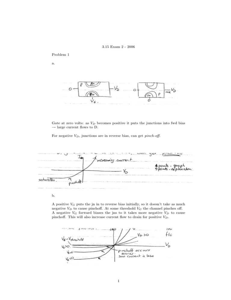
3.15 Exam 2 - 2006 Problem 1 a. Gate at zero volts: as VD becomes positive it puts the junctions into fwd bias → large current flows to D. For negative VD , junctions are in reverse bias, can get pinch-off. b. A positive VG puts the jn in to reverse bias initially, so it doesn’t take as much negative VD to cause pinchoff. At some threshold VG the channel pinches off. A negative VG forward biases the jns to it takes more negative VD to cause pinchoff. This will also increase current flow to drain for positive VD . 1 For positive VG , if we have a positive VD it will counteract the VG and current will flow. c. • Easier to fabricate - channel width formed by inversion, not lithography. • Uses the Si-Si)2 interface which is well controlled. • Lower power use - by combining the p & n channel device get CMOS which is very low power. • Can make MOS-capacitor at same time ⇒ DRAM. 2 Problem 2 a. Phosphor absorbs UV light and re-emits the energy at a wavelength determined by composition of phosphor. For example: Blue: ZnS + Ag Green: (Zn,Cd)S + Cu Red: H2 O2 S + Eu, Tb These are ≈ 1 µm particles. To get white, mix all three together at appropriate ratios. b. For exciting the blue phosphor, we need something with bandgap in near UV. For example: ZnS (3.6 eV) → use a Si substrate or ZnS. Blue = 460 nm = -2.7 eV. The only other options are MnSe or MnTe based materials which would be grown as a heterostructure on MnSe or InP substrates for the MnSe laser or MnTe substrate for the MnTe heterostructure. We can also use GaN - not shown on plot, but it grows on Al2 O3 with 3.4 eV band gap. c. Use p-i-n structure: i material has lower gap. fwd bias: e enter potential well from n-side; holes from p side. They are trapped 3 and must recombine. LED: width ≈ 1.8 kT (20 nm in red) due to excitons, fermi distribution. Laser: width few nm since amplification only of center frequencies. Both show modes (2d = N λ with N an integer.) d. 0.1 mm laser ⇒ only get light output when v = cN/2d, (c = vλ) ⇒ λ = 2d/N . If we have eg 3 eV laser light, λ = 410 nm, then for 2d = 200 µm = 2 · 10−4 m = 2 · 105 nm so N ≈ 487.8. So we will get modes like: N λ 487 410.6 nm 488 409.8 nm 489 408.9 nm Modes separated by about 0.9 nm in wavelength. We probably get only a few modes because the output is typically only a few nm wide for a laser diode. 4 Problem 3 a. I -9 8.5 8 7.5 6 4 V Power (W) 4 36 8 68 10.5 84 12 90 ← best 14 84 16764 b. V = I(Rpv + RL ) 12 = 1.6Ω ⇒ RL = 1.4Ω 7.5 Note: This is a very low resistance so you can’t connect any device across it ­ you have a large current, small voltage; possibly use to charge a battery, etc. (Rpv + RL ) = c. For a Si Cell: Antireflective coating on top surface. Dimples on top surface by etching. Reflective lower surface. Transparent top contacts or make them as narrow as practical. Mirrors to reflect light onto solar cell. Non-Si Cells: use multiple band gaps to get much higher efficiency. d. A Si has direct gap because carrier momentum is not well defined. This is because carriers are localized by the nonuniformities in the structure which gives a non-flat energy landscape. Since their position is determined (to some extent) then momentum has a nonzero uncertainty (δxδp ≥ h̄) and it is possible for a direct absorption process to occur. 5


