3.15 Electrical, Optical and Magnetic Materials and Devices Fall 2006
advertisement
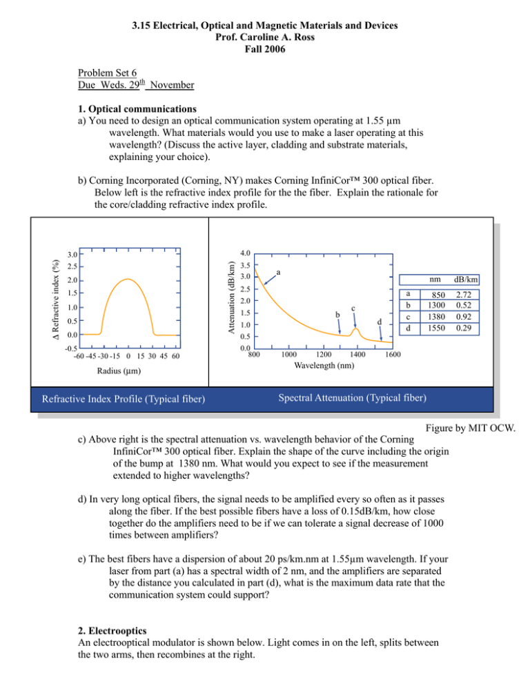
3.15 Electrical, Optical and Magnetic Materials and Devices Prof. Caroline A. Ross Fall 2006 Problem Set 6 Due Weds. 29th November 1. Optical communications a) You need to design an optical communication system operating at 1.55 µm wavelength. What materials would you use to make a laser operating at this wavelength? (Discuss the active layer, cladding and substrate materials, explaining your choice). 3.0 4.0 2.5 3.5 3.0 Attenuation (dB/km) ∆ Refractive index (%) b) Corning Incorporated (Corning, NY) makes Corning InfiniCor™ 300 optical fiber. Below left is the refractive index profile for the the fiber. Explain the rationale for the core/cladding refractive index profile. 2.0 1.5 1.0 0.5 0.0 -0.5 -60 -45 -30 -15 0 15 30 45 60 Radius (µm) Refractive Index Profile (Typical fiber) a 2.5 2.0 1.5 1.0 0.5 0.0 800 b 1000 1200 a b c d c d 1400 nm dB/km 850 1300 1380 1550 2.72 0.52 0.92 0.29 1600 Wavelength (nm) Spectral Attenuation (Typical fiber) Figure by MIT OCW. c) Above right is the spectral attenuation vs. wavelength behavior of the Corning InfiniCor™ 300 optical fiber. Explain the shape of the curve including the origin of the bump at 1380 nm. What would you expect to see if the measurement extended to higher wavelengths? d) In very long optical fibers, the signal needs to be amplified every so often as it passes along the fiber. If the best possible fibers have a loss of 0.15dB/km, how close together do the amplifiers need to be if we can tolerate a signal decrease of 1000 times between amplifiers? e) The best fibers have a dispersion of about 20 ps/km.nm at 1.55µm wavelength. If your laser from part (a) has a spectral width of 2 nm, and the amplifiers are separated by the distance you calculated in part (d), what is the maximum data rate that the communication system could support? 2. Electrooptics An electrooptical modulator is shown below. Light comes in on the left, splits between the two arms, then recombines at the right. V waveguide Light in Light out a) The grey part of the upper arm represents an electrooptical material whose optical properties can be controlled by applying a voltage V. Explain how this device can be used to modulate light. Draw a sketch of transmission of light vs. applied voltage. b) Where in an optical communications system would you use this device? c) If the electrooptical material is 10 microns wide and 1 mm long, and it has a refractive index of 2 and a Pockels coefficient of 10–10 m/V, how much voltage do you need to apply to modulate 1500 nm wavelength light? d) What type of materials show electrooptical effects? Give examples e) Suppose the electrooptical material has an attenuation of 10 dB/cm, while the rest of the device has negligible attenuation. What effect will this have on the performance of the device? (be as quantitative as you can). 3. Magnetic Basics a) Describe in 1-2 sentences the following materials classes terms of their values of μr (relative permeability) or hysteresis loops, and the way the magnetizations of the individual atoms are arranged in the material: diamagnetic, paramagnetic, ferromagnetic, ferrimagnetic, antiferromagnetic (b) Explain the shapes of the lines of B, H and M in and around a rectangular bar magnet (assume that there is zero externally applied field). (c) In the MKS system, all units can be represented by a combination of meters, kg, sec and coulombs. Express the following units as combinations of the basic units: joule, pascal, volt, ohm, farad, weber, tesla, henry. (d) What is the difference between the following: B-H loops and M-H loops Coercivity, remanence and permeability Hysteresis loss and eddy current loss

