Likun Wang , Bing Zhang , Denis Tremblay , and Yong Han
advertisement
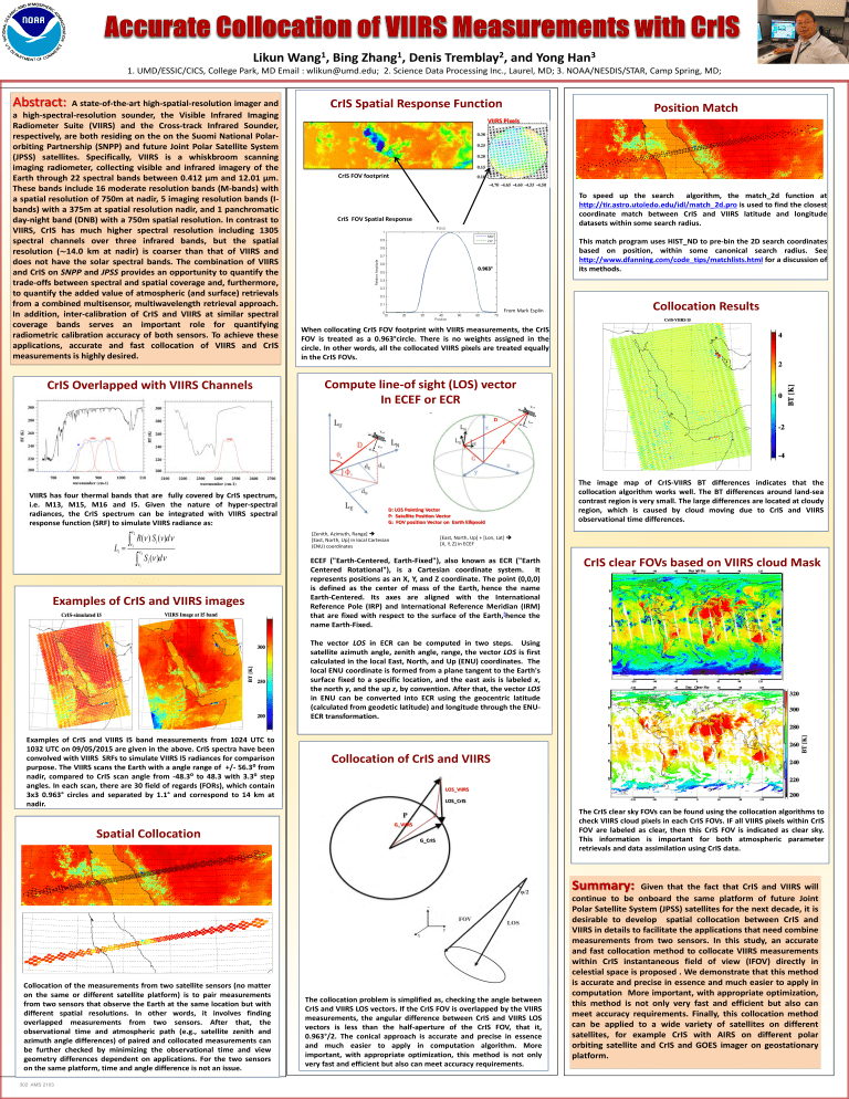
Likun 1 Wang , Bing 1 Zhang , Denis 2 Tremblay , and Yong 3 Han 1. UMD/ESSIC/CICS, College Park, MD Email : wlikun@umd.edu; 2. Science Data Processing Inc., Laurel, MD; 3. NOAA/NESDIS/STAR, Camp Spring, MD; A state-of-the-art high-spatial-resolution imager and a high-spectral-resolution sounder, the Visible Infrared Imaging Radiometer Suite (VIIRS) and the Cross-track Infrared Sounder, respectively, are both residing on the on the Suomi National Polarorbiting Partnership (SNPP) and future Joint Polar Satellite System (JPSS) satellites. Specifically, VIIRS is a whiskbroom scanning imaging radiometer, collecting visible and infrared imagery of the Earth through 22 spectral bands between 0.412 μm and 12.01 μm. These bands include 16 moderate resolution bands (M-bands) with a spatial resolution of 750m at nadir, 5 imaging resolution bands (Ibands) with a 375m at spatial resolution nadir, and 1 panchromatic day-night band (DNB) with a 750m spatial resolution. In contrast to VIIRS, CrIS has much higher spectral resolution including 1305 spectral channels over three infrared bands, but the spatial resolution (∼14.0 km at nadir) is coarser than that of VIIRS and does not have the solar spectral bands. The combination of VIIRS and CrIS on SNPP and JPSS provides an opportunity to quantify the trade-offs between spectral and spatial coverage and, furthermore, to quantify the added value of atmospheric (and surface) retrievals from a combined multisensor, multiwavelength retrieval approach. In addition, inter-calibration of CrIS and VIIRS at similar spectral coverage bands serves an important role for quantifying radiometric calibration accuracy of both sensors. To achieve these applications, accurate and fast collocation of VIIRS and CrIS measurements is highly desired. CrIS Overlapped with VIIRS Channels CrIS Spatial Response Function Position Match VIIRS Pixels CrIS FOV footprint To speed up the search algorithm, the match_2d function at http://tir.astro.utoledo.edu/idl/match_2d.pro is used to find the closest coordinate match between CrIS and VIIRS latitude and longitude datasets within some search radius. CrIS FOV Spatial Response This match program uses HIST_ND to pre-bin the 2D search coordinates based on position, within some canonical search radius. See http://www.dfanning.com/code_tips/matchlists.html for a discussion of its methods. 0.963° From Mark Esplin Collocation Results When collocating CrIS FOV footprint with VIIRS measurements, the CrIS FOV is treated as a 0.963°circle. There is no weights assigned in the circle. In other words, all the collocated VIIRS pixels are treated equally in the CrIS FOVs. Compute line-of sight (LOS) vector In ECEF or ECR D P VIIRS has four thermal bands that are fully covered by CrIS spectrum, i.e. M13, M15, M16 and I5. Given the nature of hyper-spectral radiances, the CrIS spectrum can be integrated with VIIRS spectral response function (SRF) to simulate VIIRS radiance as: ν2 ∫ L= ν1 i R(ν ) Si (v )dν ν2 ∫ ν1 Si (ν )dν Examples of CrIS and VIIRS images D: LOS Pointing Vector P: Satellite Position Vector G: FOV position Vector on Earth Ellipsoid [Zenith, Azimuth, Range] [East, North, Up] in local Cartesian (ENU) coordinates The image map of CrIS-VIIRS BT differences indicates that the collocation algorithm works well. The BT differences around land-sea contrast region is very small. The large differences are located at cloudy region, which is caused by cloud moving due to CrIS and VIIRS observational time differences. [East, North, Up] + [Lon, Lat] [X, Y, Z] in ECEF ECEF ("Earth-Centered, Earth-Fixed"), also known as ECR ("Earth Centered Rotational"), is a Cartesian coordinate system. It represents positions as an X, Y, and Z coordinate. The point (0,0,0) is defined as the center of mass of the Earth, hence the name Earth-Centered. Its axes are aligned with the International Reference Pole (IRP) and International Reference Meridian (IRM) that are fixed with respect to the surface of the Earth,[hence the name Earth-Fixed. CrIS clear FOVs based on VIIRS cloud Mask The vector LOS in ECR can be computed in two steps. Using satellite azimuth angle, zenith angle, range, the vector LOS is first calculated in the local East, North, and Up (ENU) coordinates. The local ENU coordinate is formed from a plane tangent to the Earth's surface fixed to a specific location, and the east axis is labeled x, the north y, and the up z, by convention. After that, the vector LOS in ENU can be converted into ECR using the geocentric latitude (calculated from geodetic latitude) and longitude through the ENUECR transformation. Examples of CrIS and VIIRS I5 band measurements from 1024 UTC to 1032 UTC on 09/05/2015 are given in the above. CrIS spectra have been convolved with VIIRS SRFs to simulate VIIRS I5 radiances for comparison purpose. The VIIRS scans the Earth with a angle range of +/- 56.3⁰ from nadir, compared to CrIS scan angle from -48.3⁰ to 48.3 with 3.3⁰ step angles. In each scan, there are 30 field of regards (FORs), which contain 3x3 0.963° circles and separated by 1.1° and correspond to 14 km at nadir. Spatial Collocation Collocation of the measurements from two satellite sensors (no matter on the same or different satellite platform) is to pair measurements from two sensors that observe the Earth at the same location but with different spatial resolutions. In other words, it involves finding overlapped measurements from two sensors. After that, the observational time and atmospheric path (e.g., satellite zenith and azimuth angle differences) of paired and collocated measurements can be further checked by minimizing the observational time and view geometry differences dependent on applications. For the two sensors on the same platform, time and angle difference is not an issue. 302 AMS 2103 Collocation of CrIS and VIIRS LOS_VIIRS LOS_CrIS G_VIIRS G_CrIS The collocation problem is simplified as, checking the angle between CrIS and VIIRS LOS vectors. If the CrIS FOV is overlapped by the VIIRS measurements, the angular difference between CrIS and VIIRS LOS vectors is less than the half-aperture of the CrIS FOV, that it, 0.963°/2. The conical approach is accurate and precise in essence and much easier to apply in computation algorithm. More important, with appropriate optimization, this method is not only very fast and efficient but also can meet accuracy requirements. The CrIS clear sky FOVs can be found using the collocation algorithms to check VIIRS cloud pixels in each CrIS FOVs. IF all VIIRS pixels within CrIS FOV are labeled as clear, then this CrIS FOV is indicated as clear sky. This information is important for both atmospheric parameter retrievals and data assimilation using CrIS data. Given that the fact that CrIS and VIIRS will continue to be onboard the same platform of future Joint Polar Satellite System (JPSS) satellites for the next decade, it is desirable to develop spatial collocation between CrIS and VIIRS in details to facilitate the applications that need combine measurements from two sensors. In this study, an accurate and fast collocation method to collocate VIIRS measurements within CrIS instantaneous field of view (IFOV) directly in celestial space is proposed . We demonstrate that this method is accurate and precise in essence and much easier to apply in computation More important, with appropriate optimization, this method is not only very fast and efficient but also can meet accuracy requirements. Finally, this collocation method can be applied to a wide variety of satellites on different satellites, for example CrIS with AIRS on different polar orbiting satellite and CrIS and GOES imager on geostationary platform.

![Appointments: Manual Booking using [ALT-M] in conjunction](http://s3.studylib.net/store/data/007588400_2-a89991296ab31df74067d7b72cd8b787-300x300.png)