Massachusetts Institute of Technology
advertisement
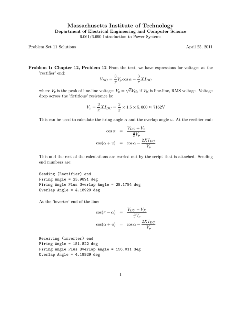
Massachusetts Institute of Technology Department of Electrical Engineering and Computer Science 6.061/6.690 Introduction to Power Systems Problem Set 11 Solutions April 25, 2011 Problem 1: Chapter 12, Problem 12 From the text, we have expressions for voltage: at the ’rectifier’ end: 3 3 VDC = Vp cos α − XIDC π π √ where Vp is the peak of line-line voltage: Vp = 6Vℓℓ , if Vℓℓ is line-line, RMS voltage. Voltage drop across the ’fictitious’ resistance is: Vx = 3 3 XIDC = × 1.5 × 5, 000 ≈ 7162V π π This can be used to calculate the firing angle α and the overlap angle u. At the rectifier end: VDC + Vx 3 π Vp 2XIDC cos(α + u) = cos α − Vp cos α = This and the rest of the calculations are carried out by the script that is attached. Sending end numbers are: Sending (Rectifier) end Firing Angle = 23.9891 deg Firing Angle Plus Overlap Angle = 28.1784 deg Overlap Angle = 4.18929 deg At the ’inverter’ end of the line: VDC − VX 3 π Vp 2XIDC cos(α + u) = cos α − Vp cos(π − α) = Receiving (inverter) end Firing Angle = 151.822 deg Firing Angle Plus Overlap Angle = 156.011 deg Overlap Angle = 4.18929 deg 1 To do the Fourier analysis, note that the AC side has alternating pulses of current with amplitude of 5,000 A and width of θ = 120◦ . The Fourier series amplitude for harmonic of order n is: In = IDC θ π 4 sin n sin n nπ 2 2 These evaluate to: Time Harmonic Amplitudes for Harmonic Order 1 Current Harmonic Order 5 Current Harmonic Order 7 Current Harmonic Order 11 Current Harmonic Order 13 Current Harmonic Order 17 Current Harmonic Order 19 Current Harmonic Order 23 Current Harmonic Order 25 Current Six Pulse Amplitude Amplitude Amplitude Amplitude Amplitude Amplitude Amplitude Amplitude Amplitude System = 5513.3 = -1102.7 = -787.6 = 501.2 = 424.1 = -324.3 = -290.2 = 239.7 = 220.5 Note the problem asks for only the first four of these, but I kept a few more to be consistent with the next part. A reconstructed time waveform is shown in Figure 1. Six Pulse AC Side 6000 4000 Amps 2000 0 −2000 −4000 −6000 0 2 4 6 8 10 12 14 omega *t Figure 1: Reconstruction of Six Pulse Waveform, harmonics to order 25 For a twelve pulse system the amplitude of the harmonics of order 5, 7, 17 and 19 all cancel. The harmonics of the other orders remain the same. This needs a little explanation: we have not considered the use of transformers here, but to have the same AC and DC voltage levels, we would need transformers of 1/2 the ratio, so each of the two transformers would contribute 2 AC harmonics of 1/2 the amplitude as in the six pulse case, but these harmonics would add, restoring the amplitude to the same level. These would then be: Harmonic Harmonic Harmonic Harmonic Harmonic Harmonic Amplitudes for Twelve Pulse System Order 1 Current Amplitude = 5513.3 Order 11 Current Amplitude = 501.2 Order 13 Current Amplitude = 424.1 Order 23 Current Amplitude = 239.7 Order 25 Current Amplitude = 220.5 The reconstructed AC waveform is shown in Figure 2. It does look a little bit more sine wave like. Twelve Pulse AC Side 6000 4000 Amps 2000 0 −2000 −4000 −6000 0 2 4 6 8 10 12 14 omega *t Figure 2: Reconstructed AC Waveform: Twelve Pulse 3 Script for Problem 12-12 % Problem 12-12 % basic parameters X = 1.5; Vl = 330e3; Vdc = 400e3; I = 5e3; % % % % leakage at each end line-line voltage (AC) DC voltage DC current % first, get that mysterious overlap voltage Vx = (3/pi)*X*I; Vp = sqrt(2)*Vl; % and this is the peak system voltage alfs = acos((Vdc+Vx)/(3*Vp/pi)); upa = acos(cos(alfs)-2*X*I/Vp); u = upa - alfs; fprintf(’Problem 12-12: Basic Analysis\n’) fprintf(’Vx = %g\n’, Vx) fprintf(’Sending (Rectifier) end\n’) fprintf(’Firing Angle = %g deg\n’, (180/pi)*alfs) fprintf(’Firing Angle Plus Overlap Angle = %g deg\n’, (180/pi)*upa) fprintf(’Overlap Angle = %g deg\n’, (180/pi)*u) % other end ppa = acos((Vdc- Vx)/((3/pi)*Vp)); alfr = pi - ppa; apu = acos(cos(alfr) - 2*X*I/Vp); ur = apu - alfr; fprintf(’Receiving (inverter) end\n’) fprintf(’Firing Angle = %g deg\n’, (180/pi)*alfr) fprintf(’Firing Angle Plus Overlap Angle = %g deg\n’, (180/pi)*apu) fprintf(’Overlap Angle = %g deg\n’, (180/pi)*ur) % now do some Fourier Analysis th = pi*2/3; % this is the angle of each pulse N = [1 5 7 11 13 17 19 23 25]; 4 In = I * (4/pi) .* sin(N .* th/2) .* sin(N .* pi/2) ./ N; fprintf(’Time Harmonic Amplitudes for Six Pulse System\n’) for k = 1:length(N) fprintf(’Harmonic Order %4.0f Current Amplitude = %6.1f\n’,N(k), In(k)) end % now let’s construct a figure of this omt = 0:.001:4*pi; Iac = zeros(size(omt)); for k = 1:length(N) Iac = Iac + In(k) .* sin (N(k) .* omt); end figure(1) plot(omt, Iac) title(’Six Pulse AC Side’) ylabel(’Amps’) xlabel(’omega *t’) % now consider the 12-pulse situation N = [1 11 13 23 25]; In = I * (4/pi) .* sin(N .* th/2) .* sin(N .* pi/2) ./ N; fprintf(’Harmonic Amplitudes for Twelve Pulse System\n’) for k = 1:length(N) fprintf(’Harmonic Order %4.0f Current Amplitude = %6.1f\n’,N(k), In(k)) end % now let’s construct a figure of this Iac = zeros(size(omt)); for k = 1:length(N) Iac = Iac + In(k) .* sin (N(k) .* omt); end figure(2) plot(omt, Iac) title(’Twelve Pulse AC Side’) ylabel(’Amps’) 5 xlabel(’omega *t’) 6 Problem 2, part a: 14-2 With terminal voltage of 100 volts and 10 amperes flowing through 21 Ω internal voltage is: GΩIf = 95V which means that G= 95 ≈ 0.528H 180 × 1 And peak torque is T = 10 × 0.528 ≈ 5.28N-m Problem 2, Part b: 14-5 This is not as nasty a problem as it sounds. Note that we can easily calculate the motor constant: since GΩI + RI = V , G= V − RI ΩI And, since power is P = GΩI 2 , we can find I for a given value of real power if we also know speed (which we do): P I2 = GΩ So then to find speed vs. voltage, we do a cross plot: for the range of speed, we find power: P = P0 � Ω Ω0 �3 then calculate current according to the expression above, and then V = (GΩ + R)I The result is plotted in Figure 3. Note a mistake in captioning (the figure identifies the wrong problem). 7 Problem 12.5 1000 900 800 700 RPM 600 500 400 300 200 100 0 0 100 200 300 400 Terminal Voltage 500 600 Figure 3: Speed vs. Voltage for Series Motor 8 Script for Problem 12-5 % Problem 12.5 Nz = 1000; omz = (pi/30)*Nz; Vz = 600; Iz = 800; Pz = 400e3; R = 1/8; G = (Vz-R*Iz)/(Iz*omz); om = omz .* (0:.001:1); P = Pz .* (om ./ omz) .^3; I = sqrt(P ./ (G .* om)); V = (G .* om + R) .* I; N = (30/pi) .* om; figure(1) plot(V, N); title(’Problem 12.5’) ylabel(’RPM’) xlabel(’Terminal Voltage’) grid on 9 Problem 3: 14-7 This is a piecewise linear situation that can be solved in each of three regions with the solutions patched together. In each region we have internal voltage: N N0 R0 IF Ea = Ea = Ea = N N0 N N0 0 < IF < 1 (E1 + R1 (IF − 1)) 1 < IF < 2 (E2 + R2 (IF − 1)) 2 < IF We can get minimum self-excitation speed by matching internal voltage with required voltage to make field current: N = N0 Ra + RF R0 ≈ 450RPM We could also write the second and third expressions as: Ea = Ea = N (V1 + R1 IF ) N0 N (V2 + R2 IF ) N0 Where, from the figure we have extracted the following data: R0 = 200Ω R1 = 50Ω 50 Ω R2 = 3 E1 = 200V E2 = 250V V2 = 150V 650 V2 = V 3 Note the equivalent circuit for the machine is shown in Figure 4. I L Ra Rf Ea Figure 4: Equivalent Circuit So that terminal voltage and field current are: V = Ea If = RF RF Ra − IL RF + Ra RF + Ra V RF 10 Problem 14−7: Dynamo 400 350 300 Volts 250 200 150 100 50 0 10 20 30 40 50 Output Current, A 60 70 80 90 Figure 5: Voltage vs. Load Current Now, we know the ranges of field current (1 A to 2 A and 2 A to the maximum, which is when: N V2 IF max = = 5A N0 Ra + RF − NN R2 0 I is straightforward to get IL in terms of IF : IL = IL = N N0 V1 Ra N N0 V2 Ra − IF − IF Ra +RF − NN R1 0 Ra Ra +RF − NN R2 0 Ra 1 < IF < 2 2 < IF < IF max Then, for each of the two segments, first internal and then terminal voltage can be found: Ea1 = Ea2 = N (V1 + R1 IF 1 ) N0 N (V2 + R2 IF 2 ) N0 The plot of voltage with load current is shown in Figure 5. To’flat compound’, note that, with the addition of a series field: V = Ea = RF Ra RF Ea − IL RF + Ra Ra + RF N N (V2 + R2 IF ) + RS IL N0 N0 11 where RS would be the characteristic of the series field. This suggests that terminal voltage V can be written out as: V = RF RF + Ra � Ra RF N N (V2 + R2 IF ) + Rs IL − IL N0 N0 Ra + RF � If the machine is indeed flat compounded so that V is constant, variations in IF will not be of interest, so that what we need is for: N Ra RF RF Rs = RF + Ra N0 Ra + RF We can accomplish this for only one speed, for which Rs = N0 Ra N Now, the effective constant of a field winding is proportional to the number of turns, so if Nts is the number of turns of the series field and Ntf is the number of turns of the shunt field, so that: Nts RS = R2 Ntf Then required number of turns of the series field will be: Nts = Ntf RS N0 Ra 500 2 = 48turns = Ntf = R2 N R2 1.25 50 3 12 Script for Problem 14-7 % Problem 14-7 Ra = 2; Rf = 73; E1 = 200; E2 = 250; R0 = 200; R1 = 50; R2 = 50/3; V1 = E1 - R1; V2 = E2 - 2*R2; N0 = 1200; N =1500; % first break point is in speed Ne = N0*(Ra+Rf)/R0; fprintf(’Excitation Speed = %g RPM\n’, Ne) I_f1 = 1:.01:2; I_fmax = (N/N0)*V2 / (Ra+Rf-(N/N0)*R2); V_oc = (N/N0)*(V2 + R2 * I_fmax); fprintf(’Open Circuit Voltage at %g RPM = %g\n’, N, V_oc) I_f2 = 2:.01:I_fmax; I_L1 = (N/N0)*(V1/Ra) - I_f1 .* (Ra+Rf-(N/N0)*R1)/Ra; I_L2 = (N/N0)*(V2/Ra) - I_f2 .* (Ra+Rf-(N/N0)*R2)/Ra; figure(1) plot(I_f1, I_L1, I_f2, I_L2) Ea1 = (N/N0) .*(V1 + R1 .* I_f1); Ea2 = (N/N0) .*(V2 + R2 .* I_f2); Vt1 = Ea1 .* Rf/(Ra+Rf) - (Ra*Rf/(Ra+Rf)) .* I_L1; Vt2 = Ea2 .* Rf/(Ra+Rf) - (Ra*Rf/(Ra+Rf)) .* I_L2; figure(2) plot(I_L1, Vt1, I_L2, Vt2) 13 Problem 4: Chapter 15, Problem 12 Peak torque is achieved when terminal current is exactly in quadrature with internal flux, in which case: T = 3 3 pλ0 I0 = × 2 × 0.4 × 4 = 4.8 N-m 2 2 With that torque, and noting that 4000 RPM = 418.9Radians/second, P = ωT = 418.9 × 4.8 ≈ 2011 Watts and with that condition, reactive voltage is in quadrature to internal voltage and terminal voltage is: Eint = 2 × 418.9 × .4 ≈ 335.1V (peak) Vx = 2 × 418.9 × .05 × 4 ≈ 167.6V (peak) 2 2 Vph = Eint + Vx2 √ Vℓℓ = 3 × Vph ≈ 459V (peak) The machine can produce no torque when all terminal voltage is used to drive negative current in the d- axis to keep total current within rated: V = L0 (isc − imax ) ω Short circuit current is: isc = so λ0 0.4 = ≈ 8A L0 .05 V = .05 × (8 − 4) = .2 ω or ω= Or, ωm = V ≈ 1, 873.5 0.2 ω ≈ 936.75 radians/second ≈ 8945 RPM p 14 Problem 5: PWM The whole story is told by the script (which was the point of this problem: to write the script). the developed waveform is shown in Figure 6. PWM Waveform of a Sine Wave: Amplitude = 1 1 0.8 0.6 On vs. Off 0.4 0.2 0 −0.2 −0.4 −0.6 −0.8 −1 0 0.005 0.01 0.015 0.02 Time, Sec 0.025 0.03 0.035 Figure 6: PWM Waveform The fourier analysis of this is, for an amplitude of the fundamental of one (same as the triangle wave) is: Fourier Analysis: fundemantal amplitude is 1 Harmonic 1 Amplitude = 0.999913 Harmonic 3 Amplitude = 0.000567261 Harmonic 5 Amplitude = 0.000557752 Harmonic 7 Amplitude = 0.000237784 Harmonic 9 Amplitude = 0.000238947 Harmonic 11 Amplitude = 9.1488e-05 Harmonic 13 Amplitude = -0.000103999 Harmonic 15 Amplitude = -0.000511369 Harmonic 17 Amplitude = -0.000412687 Harmonic 19 Amplitude = -0.000199636 Harmonic 21 Amplitude = -0.000310145 Harmonic 23 Amplitude = -0.000395562 Harmonic 25 Amplitude = -0.000803646 Harmonic 27 Amplitude = -0.000726942 Harmonic 29 Amplitude = -0.0013009 Harmonic 31 Amplitude = -0.00202079 Harmonic 33 Amplitude = -0.00553536 Harmonic 35 Amplitude = -0.0346489 For reduced amplitude, the harmonic content is: 15 Fourier Analysis: fundemantal amplitude is 0.25 Harmonic 1 Amplitude = 0.252131 Harmonic 3 Amplitude = 0.00103508 Harmonic 5 Amplitude = 0.00061986 Harmonic 7 Amplitude = 0.00038121 Harmonic 9 Amplitude = 0.000156627 Harmonic 11 Amplitude = 0.000260912 Harmonic 13 Amplitude = 3.41741e-06 Harmonic 15 Amplitude = 7.81786e-05 Harmonic 17 Amplitude = -0.000184951 Harmonic 19 Amplitude = 0.000229312 Harmonic 21 Amplitude = -0.000290529 Harmonic 23 Amplitude = 0.000140973 Harmonic 25 Amplitude = -0.000277316 Harmonic 27 Amplitude = -0.000161898 Harmonic 29 Amplitude = -0.00070203 Harmonic 31 Amplitude = -0.000270523 Harmonic 33 Amplitude = -0.00114894 Harmonic 35 Amplitude = -0.00167895 16 Script for Problem 5 f = 60; fp = 2400; T = 1/30; d = 1e-6; % % % % basic electrical frequency PWM frequency do it for two cycles 1 microsecond increments [t, wp] = triangle(fp, T, d); %Here is your basic triangle waveform wm = -wp; % positive and negative halves s = sin(2*pi*f .* t); % sine wave of fundamental frequency pp = s > wp; pm = s < wm; % positive half test % negative half test pwm = pp - pm; % this should be the whole thing figure(2) clf plot(t, pwm) title(’PWM Waveform of a Sine Wave: Amplitude = 1’) ylabel(’On vs. Off’) xlabel(’Time, Sec’) % ok: now do a little fourier analysis Nh = 1:2:35; fprintf(’Fourier Analysis: fundemantal amplitude is 1\n’) for k = 1:length(Nh) sn = sin(2*pi*Nh(k)*f .*t); fn = 2*sum(sn .* pwm) / length(t); fprintf(’Harmonic %3.0f Amplitude = %g\n’, Nh(k), fn); end s = .25*sin(2*pi*f .* t); % sine wave of fundamental frequency pp = s > wp; pm = s < wm; % positive half test % negative half test pwm = pp - pm; % this should be the whole thing fprintf(’Fourier Analysis: fundemantal amplitude is 0.25\n’) 17 for k = 1:length(Nh) sn = sin(2*pi*Nh(k)*f .*t); fn = 2*sum(sn .* pwm) / length(t); fprintf(’Harmonic %3.0f Amplitude = %g\n’, Nh(k), fn); end figure(3) clf plot(t, pwm) figure(4) clf plot(t, s, t, wm) ---------------function [t, w] = triangle(f, T, d) % generates a triangle wave of amplitude 1 % frequency f % length T % increment d T_c = 1/f; Ni = floor(.5*T_c/d); Nc = floor(T*f); %pause % length of one cycle % number of increments per half cycle % number of cycles % build first cycle ws = (0:Ni-1) ./ (Ni-1); wt = (Ni-1:-1:0) ./ (Ni-1); wc = [ws wt]; % first half cycle % second half cycle % first full cycle w = wc; % start concatenating for k = 1:Nc-1, w = [w wc]; end % all done t = 0:d:d*(length(w)-1); % so t is the same length as w 18 MIT OpenCourseWare http://ocw.mit.edu 6.061 / 6.690 Introduction to Electric Power Systems Spring 2011 For information about citing these materials or our Terms of Use, visit: http://ocw.mit.edu/terms.


