MASSACHUSETTS INSTITUTE OF TECHNOLOGY Department of Electrical Engineering and Computer Science
advertisement
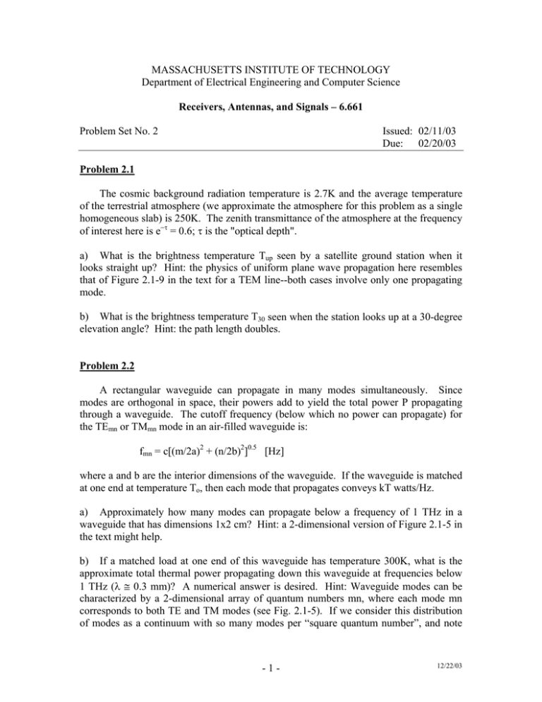
MASSACHUSETTS INSTITUTE OF TECHNOLOGY Department of Electrical Engineering and Computer Science Receivers, Antennas, and Signals – 6.661 Problem Set No. 2 Issued: 02/11/03 Due: 02/20/03 Problem 2.1 The cosmic background radiation temperature is 2.7K and the average temperature of the terrestrial atmosphere (we approximate the atmosphere for this problem as a single homogeneous slab) is 250K. The zenith transmittance of the atmosphere at the frequency of interest here is e−τ = 0.6; τ is the "optical depth". a) What is the brightness temperature Tup seen by a satellite ground station when it looks straight up? Hint: the physics of uniform plane wave propagation here resembles that of Figure 2.1-9 in the text for a TEM line--both cases involve only one propagating mode. b) What is the brightness temperature T30 seen when the station looks up at a 30-degree elevation angle? Hint: the path length doubles. Problem 2.2 A rectangular waveguide can propagate in many modes simultaneously. Since modes are orthogonal in space, their powers add to yield the total power P propagating through a waveguide. The cutoff frequency (below which no power can propagate) for the TEmn or TMmn mode in an air-filled waveguide is: fmn = c[(m/2a)2 + (n/2b)2]0.5 [Hz] where a and b are the interior dimensions of the waveguide. If the waveguide is matched at one end at temperature To, then each mode that propagates conveys kT watts/Hz. a) Approximately how many modes can propagate below a frequency of 1 THz in a waveguide that has dimensions 1x2 cm? Hint: a 2-dimensional version of Figure 2.1-5 in the text might help. b) If a matched load at one end of this waveguide has temperature 300K, what is the approximate total thermal power propagating down this waveguide at frequencies below 1 THz (λ ≅ 0.3 mm)? A numerical answer is desired. Hint: Waveguide modes can be characterized by a 2-dimensional array of quantum numbers mn, where each mode mn corresponds to both TE and TM modes (see Fig. 2.1-5). If we consider this distribution of modes as a continuum with so many modes per “square quantum number”, and note - 1 - 12/22/03 that each mode has a different propagating bandwidth, a simple integration gives an approximate answer to the total power radiated. Problem 2.3 Show that Figure 2.1-14 in the text is essentially the same for an arbitrarily shaped brief current pulse i(t) of area e coulombs, where the average current E[i] =⎯ne. Note the typographical error in the figure; it should be:⎯ne2 = e⎯i. Hint: Φ(f) is associated with the expected value of the square of the transform of an impulse having some area, as well as with the transform of an autocorrelation function; and the DC and AC portions of Φ(f) can be derived by separate methods. Problem 2.4 A certain total power radiometer is similar to the one analyzed in Section 2.2.1 in the text, but it has the bandpass filter characteristic illustrated below. What is ∆Trms for this system (i.e., what |H(f)|2 does Equation 2.2.14 become)? Hint: 4 see Section 2.2.1 in the text. B/4 B -fo 1 0 B f Problem 2.5 A certain total power radiometer employs a detector characterized by vd(t) = vi4(t) instead of the standard square-law device. Show that ∆Trms is degraded by a factor of (4/3)0.5 relative to the ideal square-law result for a boxcar bandpass filter and a boxcar integrator. Hint: Analyze the sampled version of the total-power radiometer, where the sample period is T = 1/2B, as usual. -2- 12/22/03


