International Journal of Computer Applications (0975 – 8887)
Volume 118 – No. 21, May 2015
Studying the Characteristics of a Rectangular
Waveguide using HFSS
H. Srikanth Kamath
Rachit Arora
Vriti Agarwal
Assistant Professor
Department of Electronics and
Communication
Manipal Institute of Technology,
Manipal
Student
Department of Electronics and
Communication
Manipal Institute of Technology,
Manipal
Student
Department of Electronics and
Communication
Manipal Institute of Technology,
Manipal
ABSTRACT
The Rectangular waveguides are the earliest mode of
transmission lines used for compact systems like radars and
inside equipment shelter. An air filled Rectangular waveguide
WR-90 is simulated using HFSS simulation software to obtain
different parameters. The electric and magnetic field patterns
have been analyzed, also intrinsic impedance and wavelength
for the first four modes of the waveguide are obtained. First
three modes (TE01, TE10, TE20) are included in the analysis.
Characteristic profiles are analyzed and the performance of
the waveguide is studied. Theoretical analyses have been
studied and both the results have been compared and verified.
In addition to that the cutoff wavelength has been determined
and compared with the theoretical value and its importance
has been described which can be helpful in fabricating the real
world components.
In this paper the characteristics of the rectangular waveguide
are determined by simulating through HFSS. The cutoff
frequency, radiation pattern and other near field patterns are
analyzed using this software [6]-[9].
2. MATHEMATICAL COMPUTATIONS
Rectangular Waveguide, HFSS, TE modes, Field Patterns.
A hollow rectangular waveguide is considered which is
situated in the rectangular coordinate system in which its
breadth is along the x-axis and length along the y-axis, with
inner dimensions as a*b (a>b). Air is used as the dielectric
medium. The electromagnetic waves travel in the z direction
which implies that the H component of the magnetic field Hz
must exist for the energy transmission in the waveguide. The
electromagnetic waves inside the waveguide have various
field patterns which can propagate independently and are
called modes. It is convenient to classify two-dimensional
fields as transverse magnetic (TM) or transverse electric (TE)
according to whether E or H was transverse to the direction of
propagation (or decay). The TE mn mode is characterized by Ez
1. INTRODUCTION
=0, i.e. the Hz component must exist for the transmission in
the waveguide. In TMmn modes Hz =0, and also the Ez
Keywords
Rectangular Waveguides are used to transfer electromagnetic
energy or power from one point in the space to another
efficiently. They are used in many applications such as radars,
isolators, attenuators and slotted lines.
component must exist for the transmission in the waveguide.
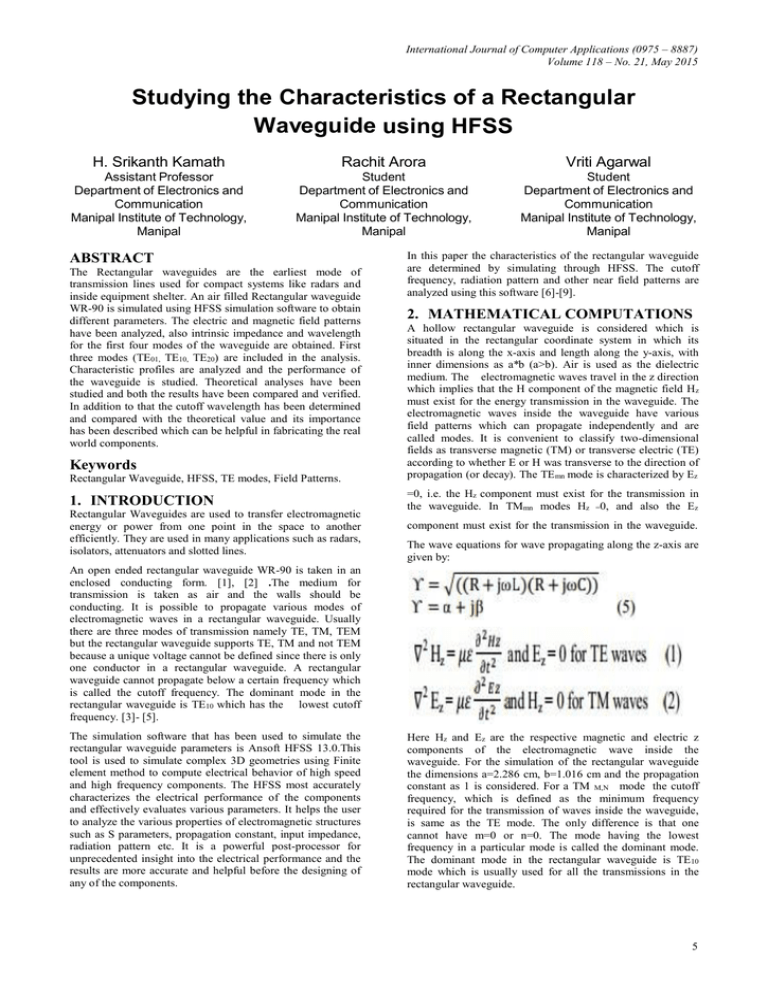
The wave equations for wave propagating along the z-axis are
given by:
An open ended rectangular waveguide WR-90 is taken in an
enclosed conducting form. [1], [2] .The medium for
transmission is taken as air and the walls should be
conducting. It is possible to propagate various modes of
electromagnetic waves in a rectangular waveguide. Usually
there are three modes of transmission namely TE, TM, TEM
but the rectangular waveguide supports TE, TM and not TEM
because a unique voltage cannot be defined since there is only
one conductor in a rectangular waveguide. A rectangular
waveguide cannot propagate below a certain frequency which
is called the cutoff frequency. The dominant mode in the
rectangular waveguide is TE10 which has the lowest cutoff
frequency. [3]- [5].
The simulation software that has been used to simulate the
rectangular waveguide parameters is Ansoft HFSS 13.0.This
tool is used to simulate complex 3D geometries using Finite
element method to compute electrical behavior of high speed
and high frequency components. The HFSS most accurately
characterizes the electrical performance of the components
and effectively evaluates various parameters. It helps the user
to analyze the various properties of electromagnetic structures
such as S parameters, propagation constant, input impedance,
radiation pattern etc. It is a powerful post-processor for
unprecedented insight into the electrical performance and the
results are more accurate and helpful before the designing of
any of the components.
Here Hz and Ez are the respective magnetic and electric z
components of the electromagnetic wave inside the
waveguide. For the simulation of the rectangular waveguide
the dimensions a=2.286 cm, b=1.016 cm and the propagation
constant as 1 is considered. For a TM M,N mode the cutoff
frequency, which is defined as the minimum frequency
required for the transmission of waves inside the waveguide,
is same as the TE mode. The only difference is that one
cannot have m=0 or n=0. The mode having the lowest
frequency in a particular mode is called the dominant mode.
The dominant mode in the rectangular waveguide is TE10
mode which is usually used for all the transmissions in the
rectangular waveguide.
5
International Journal of Computer Applications (0975 – 8887)
Volume 118 – No. 21, May 2015
Table2. TEM,N Cutoff Frequency
3. DESIGNING EQUATION
M
N
Fcm,n (GHz)
1
0
6.562
2
0
13.123
0
1
14.764
1
1
16.156
The dominant mode in TE and TM modes are clearly TE10
and TM11.
5. SIMULATIONS AND RESULTS
Fig 1: Rectangular Waveguide coordinate system
The cutoff frequency for different modes in a rectangular
waveguide is given as:
m, n = 0,1, 2....
Where a and b are the dimensions of the waveguide, which
has already been specified, and since the medium is air the
permittivity is 1.
The guided wavelength, which is defined as the distance
between the two equal phase planes along the waveguide, is
given as:
The propagation constant gamma is given as:
Where,
Fig 2: Rectangular waveguide simulation by HFSS
α= attenuation constant β=phase constant
4. THEORETICAL EXPECTED
RESULTS
The cutoff frequencies for various modes are calculated using
equation 3 for different modes and the expected results for the
different modes are shown below:
Table1. TMM,N Cutoff Frequency
M
N
Fcm,n (GHz)
1
1
16.156
1
2
30.248
2
1
19.753
The propagation constant vs frequency plot is plotted for the
four modes and the result is expected with the theoretical
result as shown in the figure 3:
Here we can see that the 4 modes TE10, TE20 , TE01 and
TM11are simulated against the propagation constant and the
resultis in accordance with the theoretical value. The cutoff
value for different modes is in accordance with the
theoretical values. A 3D plot is also plotted for the same as
shown in figure 4:
6
International Journal of Computer Applications (0975 – 8887)
Volume 118 – No. 21, May 2015
Fig 3: Plot of Frequency vs Propagation Constant
The Electric and magnetic field intensity patterns have also
been plotted. The electric field intensity decreases from top to
bottom. Figure 5 and 6 show the electric and magnetic field
intensity.
Fig4: 3D Rectangular plot for cut off frequency
for different modes
Fig5: Electric Field Intensity in a Rectangular Waveguide
7
International Journal of Computer Applications (0975 – 8887)
Volume 118 – No. 21, May 2015
7. REFERENCES
[1] S.Paramesha and A, Chakraborty “Waveguide as a nearfield measuring probe of the two element array radiator”
Progress in Electromagnetics Research PIER B, vol.
7,245-255, 2008.
[2] Jiao, C. Q,” Selective suppression of Electromagnetic
Modes in a Rectangular Waveguide by Distributed Wall
Losses”, Progress in Electromagnetics Research PIER
letters, vol. 22, pp. 119-128, 2011.
[3] Lee, C. S, Lee, S. W. and Chuang, S. L, “plot of modal
field distribution in rectangular and circular
waveguides”, IEEE transactions on microwave theory
and techniques, vol. 33, pp.271-274, 1985.
Fig 6: Magnetic field intensity in a rectangular waveguide
[4] Simon, w, wert hen, Mandy wolf F, I, „‟A novel
coplanar transmission line to rectangular waveguide
transition,‟‟ IEEE MTT-society international symposium
digest. Pp .257-260, 1998.
The colors indicate the intensity of the field decreasing from top
to bottom.
[5] Samuel Y Liao, 2008, “Microwave Devices and
Circuits” 3rd Edition Pearson Prentice Hall.
6. CONCLUSION
[6] Harrington, R. F, “Time harmonic Electromagnetic
Fields,” McGraw- Hills, New York, 1961.
A rectangular waveguide is simulated using HFSS and an
excellent match between the simulated and theoretical values has
been found. The cutoff frequency calculated theoretically matches
with the cutoff frequency found out by the simulation.
The properties of waveguide have been used to determine the
characteristics of the waveguide. The frequency used for sweep is
used more than the highest frequency of the cutoff of the last
mode. The Electric as well as the Magnetic Field Patterns have
been simulated and the results match with the theoretical analysis.
These simulations have been carried out for experimental analysis
and can be more helpful before the designing of real world
components.
IJCATM : www.ijcaonline.org
[7] C, A Balanis “Advanced Engineering Electromagnetic,”
1989, John Wiley and Sons Inc.
[8] R.E Collin, “Foundation for microwave engineering”,2nd
edition, 1992.McGraw-Hills New York.
[9] Baudrand, H, Tao, J,W, Atechian, J .”Study of radiating
properties of open ended rectangular wave guides”,
Antennas and Propagation, IEEE Transactions on pages;
1071-1077 Vol;36, Issue;8,Aug. 1988.
8


