Problem Set #9 1.050 Solid Mechanics Fall 2004 (
advertisement
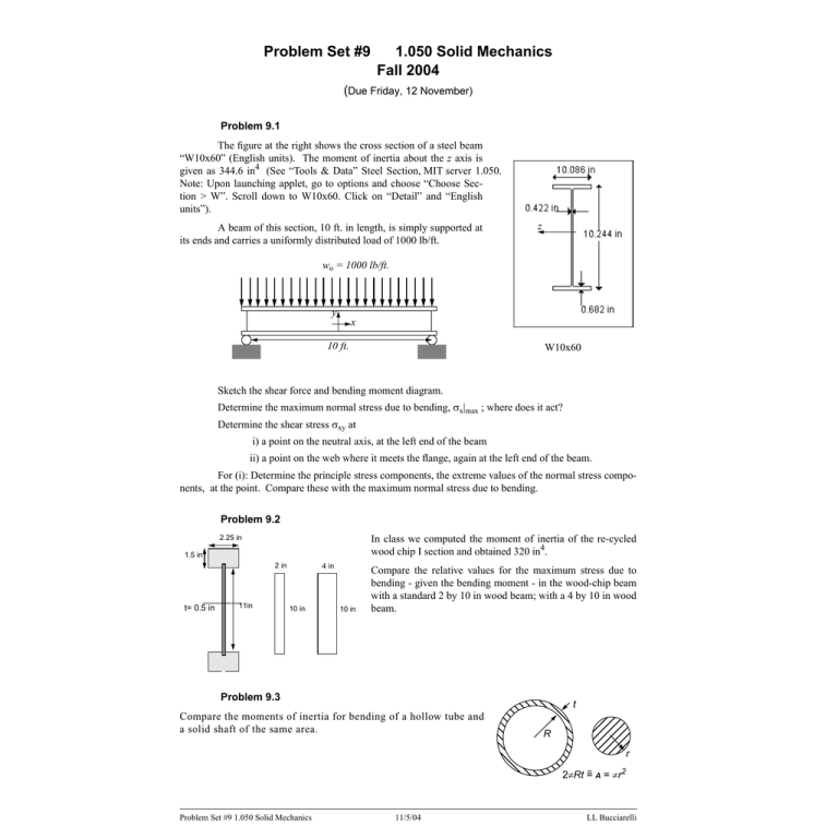
Problem Set #9 1.050 Solid Mechanics Fall 2004 (Due Friday, 12 November) Problem 9.1 The figure at the right shows the cross section of a steel beam “W10x60” (English units). The moment of inertia about the z axis is given as 344.6 in4 (See “Tools & Data” Steel Section, MIT server 1.050. Note: Upon launching applet, go to options and choose “Choose Section > W”. Scroll down to W10x60. Click on “Detail” and “English units”). A beam of this section, 10 ft. in length, is simply supported at its ends and carries a uniformly distributed load of 1000 lb/ft. z wo = 1000 lb/ft. y x 10 ft. W10x60 Sketch the shear force and bending moment diagram. Determine the maximum normal stress due to bending, σx|max ; where does it act? Determine the shear stress σxy at i) a point on the neutral axis, at the left end of the beam ii) a point on the web where it meets the flange, again at the left end of the beam. For (i): Determine the principle stress components, the extreme values of the normal stress compo­ nents, at the point. Compare these with the maximum normal stress due to bending. Problem 9.2 In class we computed the moment of inertia of the re-cycled wood chip I section and obtained 320 in4. 2.25 in 1.5 in 2 in t= 0.5 in 11in 4 in 10 in 10 in Compare the relative values for the maximum stress due to bending - given the bending moment - in the wood-chip beam with a standard 2 by 10 in wood beam; with a 4 by 10 in wood beam. Problem 9.3 t Compare the moments of inertia for bending of a hollow tube and a solid shaft of the same area. R r ~ A = πr2 2πRt = Problem Set #9 1.050 Solid Mechanics 11/5/04 LL Bucciarelli


