16.50 Lecture 16 Thrust Vectoring
advertisement
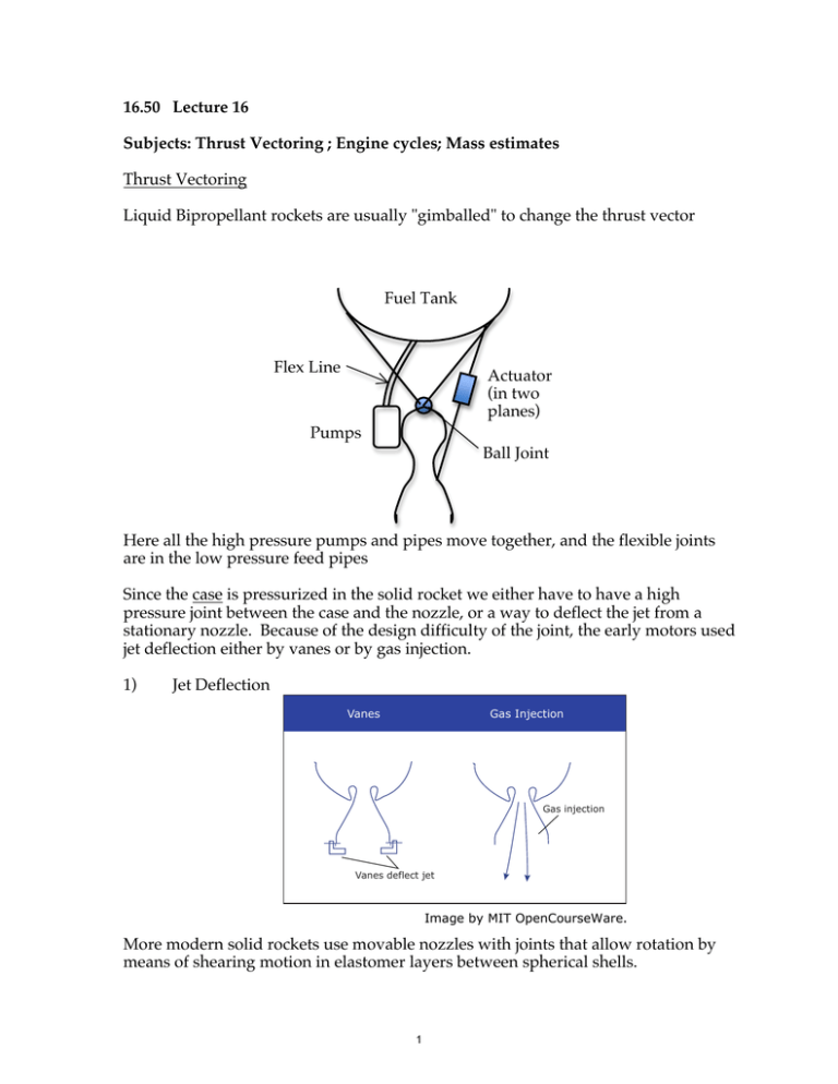
16.50 Lecture 16 Subjects: Thrust Vectoring ; Engine cycles; Mass estimates Thrust Vectoring Liquid Bipropellant rockets are usually "gimballed" to change the thrust vector Fuel Tank Flex Line Actuator (in two planes) Pumps Ball Joint Here all the high pressure pumps and pipes move together, and the flexible joints are in the low pressure feed pipes Since the case is pressurized in the solid rocket we either have to have a high pressure joint between the case and the nozzle, or a way to deflect the jet from a stationary nozzle. Because of the design difficulty of the joint, the early motors used jet deflection either by vanes or by gas injection. 1) Jet Deflection Vanes Gas Injection Gas injection Vanes deflect jet Image by MIT OpenCourseWare. More modern solid rockets use movable nozzles with joints that allow rotation by means of shearing motion in elastomer layers between spherical shells. 1 These are difficult to implement. The design issues include a) Large pressure differences b) Sealing against leaks of hot gases Schematically, the joints look like: Center of rotation Rubber in shear Image by MIT OpenCourseWare. Pressurization Systems The systems for pressurizing the propellant for injection into the combustion chamber of liquid bi-propellant rockets range from very simple gas bottle pressurization, to complex engine cycles. We have time only to outline them here, and indicate some of their advantages and disadvantages. He a) Gas bottle pressurization of fuel tanks: Advantage – Simplicity Valve Propellant Disadvantage - Weight of both gas and Propellant tanks Valve 2 b) Monopropellant or Bipropellant Gas Generator In these systems a hot gas is generated either by decomposition of a monopropellant such as H2O2 or N2H4 or by combustion of a small fraction of the main propellants. The hot gas is expanded through a turbine and dumped overboard, the turbine driving the propellant pumps. Advantage - Simple start-up even in space, and straightforward development process Disadvantage - Overboard dump of exhaust reduces the effective Isp Examples- V-2 (H2O2), Atlas, Thor, Delta, Saturn 5, Titan 3) Topping Cycle (Expander) In this system the entire fuel flow is pumped above the injection pressure, heated in the cooling jackets of the nozzle and combustion chamber, expanded through a turbine that drives the pump, then injected into the combustion chamber. 3 Advantage - High Isp and simplicity relative to the preburner systems to be described next. Disadvantages - Complex startup dependent on stored heat in system, and limit on the chamber pressure that can be achieved due to temperature limit on turbine drive gas. Example - RL-10 for Centaur 4) Preburner (Staged Combustion Cycle) This system predominates in modern high-performance engines. In US practice most if not all of the fuel is pumped to a high pressure and burned with a part of the oxidizer (to keep the temperature within the limits of the turbine), expanded through a turbine that drives the fuel and oxidizer pumps then injected into the main combustor. The central feature is that all the propellant goes through the main combustor and nozzle. In some Russian engines that use Kerosene as the fuel, the preburner operates oxidizer rich rather than fuel rich. Advantages - Ability to operate at very high chamber pressures, high Isp, and flexibility of a cycle design. Disadvantages - Complexity of design construction and startup, high cost, high pump delivery pressures. 6) Tank Weights (connected to pressure) How thick do the tank wals need to be? Balancing the pressure forces against the hoop stress in a cylindrical chamber, t p pD = 2σt ! D = 2σ Assume the cylinder, of length L is terminated with two hemispherical caps: 4 L Mass = ρt[πDL + πD2] = πρD2t[1 + D ] D2 D3 1 1L Vol = π [ 4 L + 6 ] = πD3[ 6 + 4 D ] L L L Mass t 1+D t 1+D p 1+D Vol = ρ D 1 1 L = 4ρ D 2 L = 2ρt σ 2 L 6+4D 3+D 3+D L ρt p 1 + D Tank mass Prop mass = 2 ρp σ 2 L 3+D Example: Pressure-fed Hydrazine (N2H4), Nitrogen Tetroxide (N2O4 ) pc = 20 atm = 2.03x10⁶Pa, ρHydrazine =995 kg/m 3 ρt = 4,100 kg/m3, σ ≈ 8x10⁸ Pa L L 1+ Tank mass 4100 2.03 1+ D D Prop mass ~ 2 62995 800 2 L ~ .021 2 L + + 3 D 3 D Titanium alloy or about 0.03-0.04 when attachments are added. Example: Including thrust load During engine operation, the pressure at the bottom of the tank (of length L) is p = p0 + n! p gL , and this should replace p0 in the calculation. Here n is the sum of gravity and acceleration, divided by gravity (i.e., the effective gravity, in g’s). If the hydrostatic second term dominates, as it may in long tanks, then we get MTank ! gL 1+ L /D = 2n t M Pr op. " 2 /3 + L /D Suppose acceleration is 4 g's, the tank length is 30 m, and other data are as before (except that propellant mass does not matter now). We calculate Tank mass 1+ L /D Prop mass = 0.012 2 /3 + L /D so the static part of the pressure still dominates, but thrust loading does matter. Note the scaling - worse for large vehicles in this case. 5 MIT OpenCourseWare http://ocw.mit.edu 16.50 Introduction to Propulsion Systems Spring 2012 For information about citing these materials or our Terms of Use, visit: http://ocw.mit.edu/terms.
