16.30/31 September 24, 2010 Due: October 15, 2010
advertisement

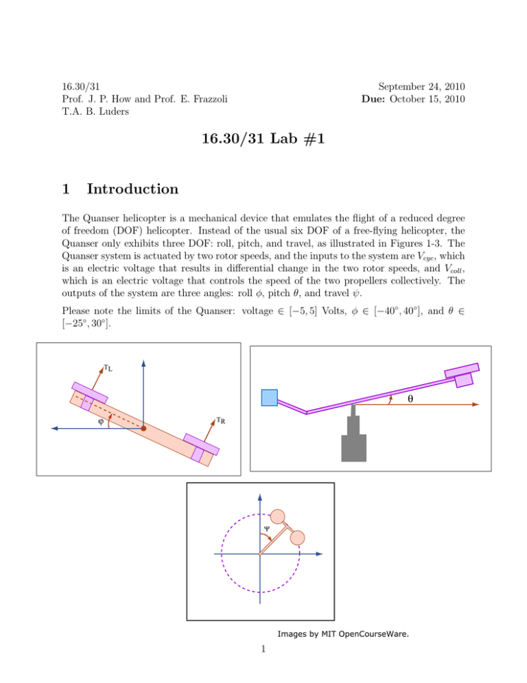
16.30/31 Prof. J. P. How and Prof. E. Frazzoli T.A. B. Luders September 24, 2010 Due: October 15, 2010 16.30/31 Lab #1 1 Introduction The Quanser helicopter is a mechanical device that emulates the flight of a reduced degree of freedom (DOF) helicopter. Instead of the usual six DOF of a free-flying helicopter, the Quanser only exhibits three DOF: roll, pitch, and travel, as illustrated in Figures 1-3. The Quanser system is actuated by two rotor speeds, and the inputs to the system are Vcyc , which is an electric voltage that results in differential change in the two rotor speeds, and Vcoll , which is an electric voltage that controls the speed of the two propellers collectively. The outputs of the system are three angles: roll φ, pitch θ, and travel ψ. Please note the limits of the Quanser: voltage ∈ [−5, 5] Volts, φ ∈ [−40◦ , 40◦ ], and θ ∈ [−25◦ , 30◦ ]. TL θ ϕ TR Ψ Images by MIT OpenCourseWare. 1 2 Physical Model The Quanser model is derived by applying Newton’s second law to the rate of change of angular momentum. The nonlinear equations of motion are Ixx φ¨ = τcyc lh − mglφ sin(φ) − Lp φ̇ − Ir ωrotor (θ̇ cos(φ) + ψ̇ sin(φ)), ˙ Iyy θ¨ = τcoll lboom cos(φ) − M glθ sin(θ + θrest ) − Dlboom sin(γ) + Ir ωrotor φ̇ − Mq θ, Izz ψ¨ = τcoll lboom sin(φ) − Dlboom cos(γ), (1) (2) (3) where D is the induced drag, τcoll is the collective thrust, and τcyc is the cyclic thrust. These forces are modeled individually as ˙ D = KD ψ, ˙ τcoll = Kτ ωcoll − Kv ψ, ˙ τcyc = Kτ ωcyc − Kv ψ, (4) (5) (6) where KD , Kτ and Kv are constant coefficients. In addition, the motor dynamics can be modeled by ω̇cyc + 6ωcyc = 780Vcyc , ω̇coll + 6ωcoll = 540Vcoll . (7) (8) The values of other parameters in this model are given in Table 1. Note that ωrotor is the rotor rotation speed, and is assumed to be constant; terms containing ωrotor represent the rotors’ contribution to angular momentum. Additionally, γ is the vehicle’s flight path angle. Table 1: Physical parameters Parameter Value Units Description m 1.15 kg mass of rotor assembly M 3.57 kg mass of whole setup lboom 0.66 m length from pivot point to heli body 0.004 m length of pendulum for roll axis lφ 0.014 m length of pendulum for pitch axis lθ 0.177 m length from pivot point to the rotor lh 0.036 Nm moment of inertia about x-axis Ixx 0.93 Nm moment of inertia about y-axis Iyy −3 4.25 × 10 N/s coefficient of thrust Kτ degs theta rest value θrest -25 m/s2 acceleration due to gravity 9.81 g roll damping coefficient [0.02, 0.2] Lp pitch damping coefficient [0.1, 0.9] Mq 2 Linearize these equations around a steady-state hover operating condition, i.e., φ˙ 0 = θ˙0 = ψ̇0 = 0, φ0 = θ0 = ψ0 = 0, ω̇cyc,0 = ω̇coll,0 = 0, and γ0 = 0. If we ignore the dynamics in travel (ψ), the pitch (θ) and roll (φ) subsystems can be represented by the block diagrams in Figure 4. In the pre-lab assignment, you will be asked to find in symbolic form (i.e., not using the tabulated parameter values) the transfer functions Mcoll (s), QP (s), Mcyc (s), and QR (s). Vcoll Collective Voltage Vcyc Cyclic Voltage Mcoll(s) Mcyc(s) ωcoll Rotor Speed (collective) ωcyc Rotor Speed (differential) QP(s) QR(s) θ Pitch Angle Φ Roll Angle Image by MIT OpenCourseWare. The linear model does not perfectly represent the dynamics of the actual Quanser for many reasons. While there are many inaccuracies, the variations in pitch and roll damping between Quansers present the largest problem. You should assume that the damping coefficients Lp and Mq for any given Quanser will be somewhere in the ranges listed in Table 1. 3 Schedule • Fri 9/24: Lab 1 assignment posted • Mon 9/27: (optional) LabVIEW software available for personal download • Wed 9/29: deadline to e-mail group members to TA; LabVIEW tutorial in lecture • Fri 10/1: Signup sheets for lab sessions available in lecture • Mon 10/4: First day of lab sessions • Wed 10/6: Lab 1 pre-lab assignment due • Thu 10/14: Last day of lab sessions • Fri 10/15: Lab 1 writeup due 3 4 Pre-Lab Assignment (due 10/6) 1. Derive the linearized model as described in Section 2, and symbolically form the transfer functions Mcoll (s), QP (s), Mcyc (s), and QR (s). When forming the transfer functions, you may assume that the rotors’ contribution to angular momentum is negligible (i.e. ωrotor = 0). 2. Use classical design techniques to develop controllers for the roll (φ) and pitch (θ) axes. You are encouraged to use Matlab/sisotool to assist you in your design. Remember that you are designing the controllers to work for the entire range of damping constants Lp and Mq . For the nominal plants (i.e., use a damping value in the middle of the range), your controllers must have the following properties: • Less than 10% error in tracking signals with frequency content up to 1 rad/s • At least 20◦ of phase margin • Maintain stability even for the worst-case damping For these controllers, write the controller transfer function and plot the following: • Bode plot of the controller • Open loop Bode plot of controller + nominal plant • Simulated closed-loop step response for a 20◦ step command • A paragraph or two describing your design strategy, predicted performance, and pros/cons of your design (Hint: Your roll (φ) controller is going to be the “inner-loop” for the travel controller in the next lab, i.e. the travel controller will be commanding roll angle. Thus it is important that your roll controller is fast and stable but not so important that it has zero steady-state error. Conversely, your pitch (θ) controller should have zero steadystate error so that you are sure to clear altitude obstacles in the next lab.) The pre-lab assignment may be submitted either in person or online ; however, you must bring a completed pre-lab assignment with you when attending a lab session in order to proceed with the lab. You must also hand in the pre-lab assignment with your lab writeup, and it will count for a substantial portion of the overall lab grade. 4 5 Lab Procedure 1. Lab sessions will take place between October 4 and October 14. You will be working in groups of four (please work with students in your class, either 16.30 or 16.31). Each member of the group must complete the pre-lab assignment, and you must submit your own lab report. 2. Specific instructions on how to build your model and construct and test your controllers in LabVIEW will be posted in the lab, We will arrange for some support in the lab if you get stuck - but recognizing that labs are generally time consuming, and the Quanser lab facility is not available 24 hours a day, please plan ahead. As a student in 16.30/31, you will be given access to download LabVIEW for use on your own computer, and will be able to run the same software used to simulate and control the Quansers in lab. Take advantage of this opportunity to get more comfortable with the software and save time in lab. 3. Apply steps of appropriate amplitude and duration; record the system output in roll and pitch. Compare with the expected response from your models, and redesign your controller gains if necessary. 4. Record and save the following four step responses (to be included in your lab writeup): • Responses 1-2: Roll step input of Δφ = +20◦ or Δφ = −20◦ , starting from φ0 = 0◦ (vehicle is level), for two different pitch angles θ at least 10◦ apart • Response 3� : Pitch step input of Δθ = +20◦ , with φ ≡ 0◦ (vehicle is level) and arbitrary starting pitch θ0 • Response 4� : Pitch step input of Δθ = +20◦ , with φ ≡ +20◦ or φ ≡ −20◦ (vehicle is rolling) and arbitrary starting pitch θ0 (These should be performed for all of your group’s working controllers. Your group may choose to come to a consensus on a working roll/pitch controller combination.) � For either of these responses, if your controller cannot maintain stability for a pitch step of this magnitude, you should instead try to perform as large of a positive (Δθ > 0) pitch step as is feasible. You should then additionally perform as large of a negative (Δθ < 0) pitch step as is feasible. 5. Once you are satisfied with the performance of your controllers on your Quanser, save your step responses and record your final controllers. Make sure you either email the data to yourself or use SecureFX to upload it into your Athena directory so that you can access it when you write your lab report. 5 6 Lab Writeup (due 10/15) The lab writeup need not be particularly formal. However, you must include the following to receive full credit: 1. Both of your classical controllers (roll and pitch). 2. The recorded step responses listed in “Lab Procedure” with the corresponding theoret­ ical responses (from your model) overlayed in the same plot. Give a brief description of the properties of each observed response (i.e., overshoot, rise time, etc.). 3. A few paragraphs discussing how well the theoretical responses from the model matched the actual responses you measured in the lab. Give reasons for any inconsistencies and explain the importance of accounting for the plant uncertainty. Please observe standard technical writing conventions (i.e., label all charts and figures, put data in tables, etc.). The lab assignment may be submitted either in person or online . 6 MIT OpenCourseWare http://ocw.mit.edu 16.30 / 16.31 Feedback Control Systems Fall 2010 For information about citing these materials or our Terms of Use, visit: http://ocw.mit.edu/terms.


