HC Diagnosis Tools & Techniques Check ignition timing (base and advance as applicable.)
advertisement
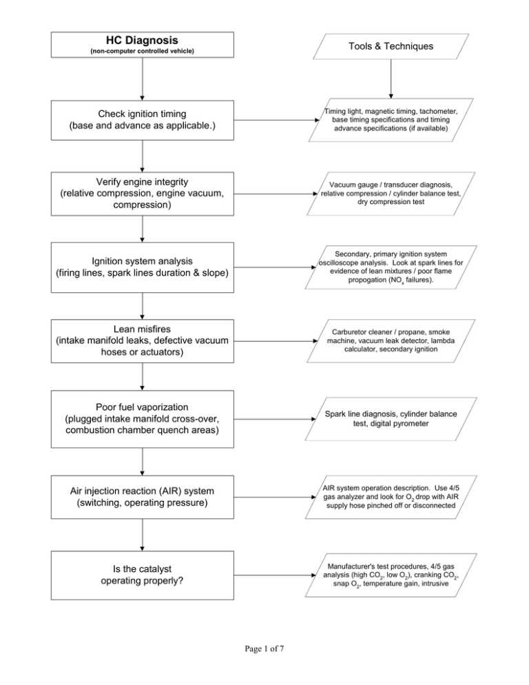
HC Diagnosis Tools & Techniques (non-computer controlled vehicle) Check ignition timing (base and advance as applicable.) Timing light, magnetic timing, tachometer, base timing specifications and timing advance specifications (if available) Verify engine integrity (relative compression, engine vacuum, compression) Vacuum gauge / transducer diagnosis, relative compression / cylinder balance test, dry compression test Ignition system analysis (firing lines, spark lines duration & slope) Secondary, primary ignition system oscilloscope analysis. Look at spark lines for evidence of lean mixtures / poor flame propogation (NOx failures). Lean misfires (intake manifold leaks, defective vacuum hoses or actuators) Carburetor cleaner / propane, smoke machine, vacuum leak detector, lambda calculator, secondary ignition Poor fuel vaporization (plugged intake manifold cross-over, combustion chamber quench areas) Spark line diagnosis, cylinder balance test, digital pyrometer Air injection reaction (AIR) system (switching, operating pressure) AIR system operation description. Use 4/5 gas analyzer and look for O2 drop with AIR supply hose pinched off or disconnected Is the catalyst operating properly? Manufacturer's test procedures, 4/5 gas analysis (high CO2, low O2), cranking CO2, snap O2, temperature gain, intrusive Page 1 of 7 HC Diagnosis Tools & Techniques (computer controlled vehicle) Refer to "High HC Non-feedback" diagnostic flowchart Timing; mechanical, electrical lean air/ fuel misfires, vaporization, AIR, catalyst DTC's? Scan tool, jumper wire, screwdriver, DTC pulling instructionis Yes Discern between hard and soft codes Pull codes, record codes in the order they are displayed, erase codes, operate vehicle, pull hard codes Follow manufacturer's or published diagnostic / repair procedures for hard codes Scan tool, multimeter, DSO, DTC diagnostic flowcharts, diagnostic & repair information Test O2S with DSO Propane enrichment tool, DSO minimum voltage = 0 - 175mV maximum = 800 - 1000mV rate of change = < 100 mS (175mV - 800 mV) No O2S in good seviceable condition? No Upon repair of O2S circuit or replacement of sensor, re-test O2S Yes High frequency signal = misfire Signal biased below 450 mV = lean mixture Signal biased above 450 mV = rich mixture Map O2S signal with DSO Page 2 of 7 CO Diagnosis Tools & Techniques (non-computer controlled vehicle) Check air intake system for restrictions Plugged / dirty air filter, improper choke operation, plugged PCV system, improper TAC operation Check for unmetered fuel entering the engine Improper EVAP purge operation, saturated EVAP cannister, fuel contaminated engine oil (> 500 ppm HC after 5 minutes measured at the oil filler neck engine off) Check carburetor operation Float level, choke operation, main metering, power valve, idle circuit Check air injection system operation Use system description / operation to verify proper switching. Check operating pressure by pinching off supply hose and verifying O2 drop in tailpipe emissions Check catalyst(s) operation After upstream repairs are complete, use manufacturer's procedures to test efficiency. Combinations of cranking CO2, snap O2, HC efficiency, temperature gain are useful when manufacturer's procedures aren't available. Page 3 of 7 Tools & Techniques CO Diagnosis (computer controlled vehicle) Refer to "High CO Non-Feedback" diagnostic flowchart Air intake restriction, unmetered fuel, carburetor, air injection, catalyst operation DTC's? Scan tool, jumper wire, screwdriver, DTC pulling instructions Yes Discern between hard and soft codes Pull codes, record codes in the order they are displayed, erase codes, operate vehicle, pull hard codes (OBD I) Follow manufacturer's or published diagnostic / repair procedures for hard codes Scan tool, multimeter, DCO, DTC diagnostic flowcharts, diagnostic & repair information Review data stream (if available) or confirm related sensor/output performance. Test O2S with DSO. DMM, DSO, propane enrichment tool, break-out box Check for vehicle computer operation (is the fuel metering system capable of being artificially driven rich or lean, is the timing being controlled? Perform manufacturer's recommended system performance check) 4/5 gas analyzer, timing light, sensor simulator No Page 4 of 7 NOx Diagnosis Tools & Techniques Check ignition timing (base and advance as applicable.) Timing light, magnetic timing, tachometer, base timing specifications and timing advance specifications (if available) Check exhaust gas recirculation (EGR) system (if equipped) Vacuum guage/pump, tachometer, scantool Check for lean air/fuel mixture Lambda calculator, gas analyzer, biased O2S pattern, fuel trim data, secondary ignition pattern Check for excessive coolant and/or intake air temperature Pyrometer, scantool, temperature probe, thermometer Check for excessive combustion chamber pressure Compression guage, borescope, TSBs Check for proper fuel octane rating Owner's manual, vehicle owner Manufacturer's test procedures, 4/5 gas analysis (high CO2, low O2), cranking CO2, snap O2, temperature gain, intrusive Check catalyst operation (vehicles equipped with a reduction catalyst only) Page 5 of 7 OBD II Diagnostics Tools & Techniques MIL illuminated? MIL functional test (KOEO bulb check) Yes No Pull DTC's and record freeze frame data Scan tool, paper & pencil. Do not erase DTC's unless instructed to do so by diagnostic / repair procedures Follow manufacturer's or published diagnostic / repair procedures for DTC's. Begin with the DTC refered to in freeze frame data Scan tool, multimeter, DSO, DTC diagnostic flowcharts, diagnostic & repair information Review pending DTC's, monitor status, mode 6 and mode 5 data, fuel trim and misfire data Scan tool Perform a system performance check and/or a complete drive cycle as per manufacturer's instructions Manufacturer's or published diagnostic & repair information Check PCM for DTC's (pending or matured), review mode 6 and mode 5 data for failed test results Scan tool Page 6 of 7 Diagnostic Preliminaries Post-diagnosis process Vehicle fails Smog Check Analyze diagnostic information (component test data, measurements, waveform analysis, etc.) Prepare an estimate for diagnosis Prepare a repair strategy based on diagnostic information Obtain customer authorization Prepare an estimate to repair defects relative to the failure determined in the diagnosis Verify customer complaint (baseline inspection in pre-inspection mode, training mode, manual mode or partial pre-inspection) when appropriate Discuss the repair strategy with the customer and obtain authorization Select a method to document diagnosis (vehicle information datasheet, tech notes, etc.) y y y y Perform authorized repairs, gauge repair effectiveness Diagnostic Assumptions Visual inspection TSB's and helpful hints Engine integrity Powers and grounds Page 7 of 7

