Research Journal of Applied Sciences, Engineering and Technology 6(16): 2988-2992,... ISSN: 2040-7459; e-ISSN: 2040-7467
advertisement
Research Journal of Applied Sciences, Engineering and Technology 6(16): 2988-2992, 2013
ISSN: 2040-7459; e-ISSN: 2040-7467
© Maxwell Scientific Organization, 2013
Submitted: January 08, 2013
Accepted: January 31, 2013
Published: September 10, 2013
The Study on Integrated Control System of A/O Sewage Wastewater Treatment Process
Jiangzhong Yu, Jihong Shan, Lijun Sheng and Yi Sun
Key Laboratory of E and M, Zhejiang University of Technology, Ministry of
Education, Zhejiang Province, Hangzhou 310032, China
Hangzhou Hengda Environment Protection Industrial Company Limited,
Hangzhou 310032, China
Abstract: Aim to solve problems of the low automatic level, high energy consumption and high labor intensity in
the process of sewage treatment and combing with the actual control requirements of the worksite, this study
introduces an integrated control system of sewage treatment. The system bases on the S7-300PLC, inverter and
KINGVIEW software. The methods of controlling, testing and management in the process of sewage treatment via
the integrated control system which consists of PLC, KINGVIEW and PC were presented. The study also discussed
the content of sewage treatment process, the component structure of control system, the control principle and the
design of hardware and software in detail. Finally, the results proved that the system can operates reliably and
effectively.
Keywords: Inverter, PLC, sewage treatment
INTRODUCTION
As we all know, it is not suitable for workers to
operate the equipments in the field because of the harsh
environment, the complex condition and so on in the
sewage treatment plant (Wang et al., 2011). So it
becomes a development tendency of modern sewage
treatment industry that the process of sewage treatment
can be achieved via automatic control and remote
monitoring. This study presents an energy-saving and
integrated automatic control system of sewage
treatment which bases on the MPI network. The system
is designed for the production process wastewater of a
new material factory. The system consists of host
computers and lower machines respectively, which
include IPC (Industrial Personal Computer),
KINGVIEW and S7-300 series PLC of siemens, smart
instrumentations and connected the components
together via KINGVIEW software (Taira et al., 2003).
This system can carries out real-time monitoring and
centralized management of the collected data such as
the field, screen monitor, parameters setting, command
control and other functions. It is convenient for workers
to check any time.
THE PROCESS OF SEWAGE TREATMENT
The sewage treatment plant uses the improved A/O
(Anoxic/Oxic) sewage treatment process as the
biochemical treatment process (Zhu et al., 2005). Some
of processed sewage is reused and the other is
discharged into river after it satisfies sewage discharge
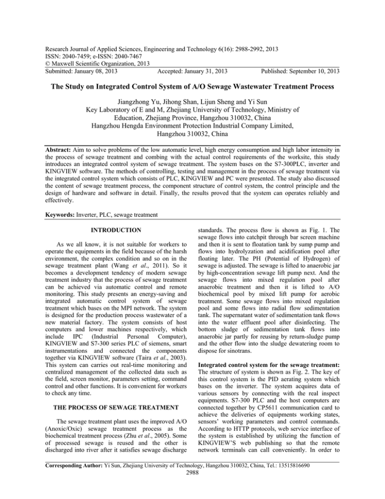
standards. The process flow is shown as Fig. 1. The
sewage flows into catchpit through bar screen machine
and then it is sent to floatation tank by sump pump and
flows into hydrolyzation and acidification pool after
floating later. The PH (Potential of Hydrogen) of
sewage is adjusted. The sewage is lifted to anaerobic jar
by high-concentration sewage lift pump next. And the
sewage flows into mixed regulation pool after
anaerobic treatment and then it is lifted to A/O
biochemical pool by mixed lift pump for aerobic
treatment. Some sewage flows into mixed regulation
pool and some flows into radial flow sedimentation
tank. The supernatant water of sedimentation tank flows
into the water effluent pool after disinfecting. The
bottom sludge of sedimentation tank flows into
anaerobic jar partly for reusing by return-sludge pump
and the other flow into the sludge dewatering room to
dispose for sinotrans.
Integrated control system for the sewage treatment:
The structure of system is shown as Fig. 2. The key of
this control system is the PID aerating system which
bases on the inverter. The system acquires data of
various sensors by connecting with the real inspect
equipments. S7-300 PLC and the host computers are
connected together by CP5611 communication card to
achieve the deliveries of equipments working states,
sensors’ working parameters and control commands.
According to HTTP protocols, web service interface of
the system is established by utilizing the function of
KINGVIEW’S web publishing so that the remote
network terminals can call conveniently. In order to
Corresponding Author: Yi Sun, Zhejiang University of Technology, Hangzhou 310032, China, Tel.: 13515816690
2988
Res. J. App. Sci. Eng. Technol., 6(16): 2988-2992, 2013
Sewage
Bar screen machine
Catchpit
Floatation tank
Blower
风机房
room
Chemical
house
river
Water effluent
pool
Mixed regulation
pool
Anaerobic jar
Radial flow
sedimentation tank
Sludge dewatering
house
Mud cake
sinotrans
A/O biochemical
pool
Disinfecting
tank
Hydrolyzation&acidification pool
Fig. 1: The process flow of sewage wastewater treatment
the working host computer and the relevant modules are
chosen to configure the system hardware. The S7-300
system hardware configurations are shown as Fig. 3.
The hardware consists of KINGVIEW monitoring
system: In the system, the monitoring computer is Dell
OptiPlex390MT CPU, 2G RAM. King view and S7300PLC are connected by MPI drive. It can realizes the
following functions by combining with PLC control
program (Su et al., 2011):
•
•
Fig. 2: The structure of system
Communication
processor
DO
computer
DI
AO
Various controller
cabinet
Processing
equipment
Electric control
valve
AI
Various sensor
CPU313
Load’s power
module
Frequency changer
Roots blower
•
Fig. 3: The system hardware configuration
communicate with sewage treatment equipments via
remote control, the remote terminals must be able to
call the web service or web explorer.
THE HARDWARE CONSISTS OF
SEWAGE TREATMENT INTEGRATED
CONTROL SYSTEM
•
According to the control objects and system’s
design commands, the system adopts siemens-313C as
2989
It can display the running states of the equipments
and sensors’ parameters in this system. The main
picture provides a better system monitoring
interface for managers and workers, which can
display the whole process of sewage treatment, the
work states of pumps and valves, liquid level,
quantity of flow, temperature, PH, frequency of
inverter and so on.
It can display equipments failures and warning
function. This system can automatically disposes
the events and alarms. While failures happen, for
example the thermo relay is overload protection or
the breaker trips, the event can be clearly shown in
the picture. When alarms happen, for example the
excessive liquid level and temperature, this system
can quickly detect and pop up the alarm prompt
picture. And the corresponding alarm text can be
shown or printed and an alarm sound ring out to
prompt workers’ attention.
Checking the run report, operating record, realtime curve and accident record: The numerical
value of various analog quantities of the controlled
objects can be recorded and displayed on the
pictures by curves or data list. At the same time,
the worker’ operation for equipments can be
recorded into the access database in order to freely
query for managers.
Some equipment can realize automatic control by
operating on the interconnected control picture.
Here the interconnected control can be set the
interconnected control and the pumps can start or
stop when the floater moves up or down based on
Res. J. App. Sci. Eng. Technol., 6(16): 2988-2992, 2013
•
•
Temperature +
value
+
the signal of liquid level in the pool. If the liquid
level is lower than the setting value, the pump
stops and when liquid level is higher than the first
setting value, only one pump runs and when liquid
level is higher the second setting value, two pumps
run automatically.
The user management functions: In order to
control the equipments, the users should log in
firstly and according to the users’ authority, the
system automatically judges the users’ authority to
control the equipments.
The web publishing functions: Other users can
load the monitoring pictures by web explore if the
host computer publish the pictures.
PID
regulator
Electric control
valve
D/A
-
A/D
Temperature
sensor
Fig. 4: The closed-loop control scheme
Start
User login
No
Equipments
connection?Data
base connection?
THE SOFTWARE DESIGN OF THE SYSTEM
Yes
The control strategies of hardware equipments in
the system:
The PID closed-loop for opening of electric control
valve: In the sewage treatment integrated control
system, the opening of electric control valve and steam
control valve are controlled by PID closed-loop so that
the regulation pool can has a relative temperature by
controlling the flow velocity and flow quantity of hot
water. Here, the position-type PID control algorithm is:
(k ) K p {e(k ) +
u=
Monitoring center
The total process monitoring
picture of sewage treatment
Inverter parameters
Equipments states
The pictures of alarm,
trends.etc.
Equipment failures
Data base management.etc.
Analogue data realtime display
Analogue value
T
T k
∑ e( j ) + TD [e(k ) − e(k − 1)]}
T1 j =0
Report query
Report generation
Report print
By using PID unitary parameter tuning method, the
above formula is:
End
Fig. 5: The design flow of KINGVIEW
=
∆u (kT ) K p {2.45(kT ) + 3.5[(k − 1)T + 1.25e(k − 2)T ]}
By setting one parameter like KP instead of setting
four parameters like T, K P , T 1 , T D , it can simplifies the
problems and the closed-loop control scheme is shown
as Fig. 4.
The temperature of regulation pool is acquired by
S7-300 and the analog signal is converted to digital
signal by A/D. Compared with the temperature setting
value, the error can be calculated. The opening of
electric control valve can be controlled by outputting
control signal of PID regulator. The temperature
eventually can be maintained between 30 and 40°C.
The inverter controls the speed of fan: In this system,
fan is one of the main energy-consumption equipments.
However, considering the energy-consumption factor,
the concentration of dissolved oxygen of A/O
biochemical pool can be controlled by adjusting the
speed of fan. So the speed of fan is adjusted by inverter.
According to the dissolved oxygen in sewage, this
system adopts quadratic rate load for inverter to adjust
the speed of fan (Li et al., 2011). The characteristics of
blower’s torque and power are:
2
2
T=
K=
K P nL 3
T nL nL / 9950
L = KT nL , PL
where,
T L = Quadratic rate load torque
P L = Quadratic rate load power
n L = Quadratic rate load speed
K T = Quadratic rate load torque constant
K P = Quadratic rate load power constant
In the above formula that the torque is proportional
to the speed’s square and the power is proportional to
speed’s cube. So when the oxygen requirement is
decreasing, the line frequency can reduce the speed of
blower by inverter. The torque and power can be more
greatly reduced and the energy-saving target is
achieved (Bae et al., 2003).
The monitoring software design: The design quality
of monitoring software is closely reponsed to control
result and the safety of user and equipment (Gustaf,
2012). So it is extremely important to develop a set of
perfect function and high reliable software. According
to the actual requestments and condition, the design
flow of the software is shown as Fig. 5.
2990
Res. J. App. Sci. Eng. Technol., 6(16): 2988-2992, 2013
(a)
(b)
Fig. 6: (a) The main picture of monitoring system, (b) the web publishing page
Firstly, the user should enter into the login
interface and input correct username and password.
While passed user check and equipment and data base
connected successfully, the monitoring center will be
shown. Otherwise, it will return the login window. In
the monitoring center, users can click the bottoms at the
below of the desktop to switch the different pictures. If
the current picture is the whole flow picture of sewage
treatment, users can view the running state of
equipments and set the running parameters of inverter
and so on. The alarm, trend curve, running log and
other information can be seen via changing the pictures
by users.
equipment’s failure can be got clearly in the picture.
And the on-off control of motors and inverter
parameters can be controlled. The web publishing pages
is shown as Fig. 6(b) and it runs basically stable. Even
though it has a bit of delay when you change the picture,
this doesn’t affect the monitoring result. And image
transmission and real-time control can synchronously
process. Because the web publishing doesn’t support
active controls, data and curves can’t be scanned
expediently. The information of data list and related
curves’ information can be scanned on IE.
RESULTS AND DISCUSSION
This system is designed for the sewage treatment
plant of the new material factory. Now, the system has
been running more than six months and the control
system runs stable and reliable. Various indexes of
water can reach depend on the design requirements after
The main monitoring picture of the system is shown
as Fig. 6(a). In the picture, the running states of
equipments, running parameters and the reasons of
CONCLUSION
2991
Res. J. App. Sci. Eng. Technol., 6(16): 2988-2992, 2013
the sewage is processed, the equipments run well and
maintain expediently. The problems of scatter,
complexity and uncontrollability of equipments are
solved in sewage treatment plant. And this system
reaches the advanced level in the same industry
automation and satisfies the demands of saving energy
and lower maintenance cost. The goals of unattended
operation in worksite and fewer workers in central
station are achieved in this sewage treatment plant.
ACKNOWLEDGMENT
The authors acknowledge to be supported by
Zhejiang
Province
Science
and
Technology
Development of P.R. China (Grant No: 2012C13006-1)
and Advance Manufacture and Design Funding of
Zhejiang University of Technology.
REFERENCES
Bae, H., M.H. Lee, Y. Kim and C.W. Kim 2003.
Knowledge-based unmanned automation and
control system s for SBR wastewater treatment
process [J]. Artif. Life Robot., 7: 107-111.
Gustaf, O., 2012. ICA and me- A subjective review [D].
Water Res., 46(6): 1585-1624.
Li, J., 2011. Discussion on the application of control
system of energy saving fan based on PLC
and inverter [J]. Manufact. Automat., 33(12):
127-129.
Su, J. and Y. Hong, 2011. Research of remote
monotoring and control system of energy saving
control station based on PLC and king view [J].
Ind. Mine Automat., 37(2): 21-23.
Taira, H., T. Hiroshi, et al., 2003. Advanced treatment
of sewage by pre-coagulation and biological
filtration process [J]. Water Res., 37(17):
4259-4269.
Wang, Y., S. Chen, et al., 2011. Design of remote
monitoring system for sewage disposal plant [J].
Comput. Measur. Control, 19(10): 2433-2436.
Zhu, Z., Y. Hu, et al., 2005. The application of the
variable frequency drives for fan [J]. Coal Mine
Mach., 7: 5-6.
2992
