Research Journal of Applied Sciences, Engineering and Technology 7(15): 3064-3068,... ISSN: 2040-7459; e-ISSN: 2040-7467
advertisement
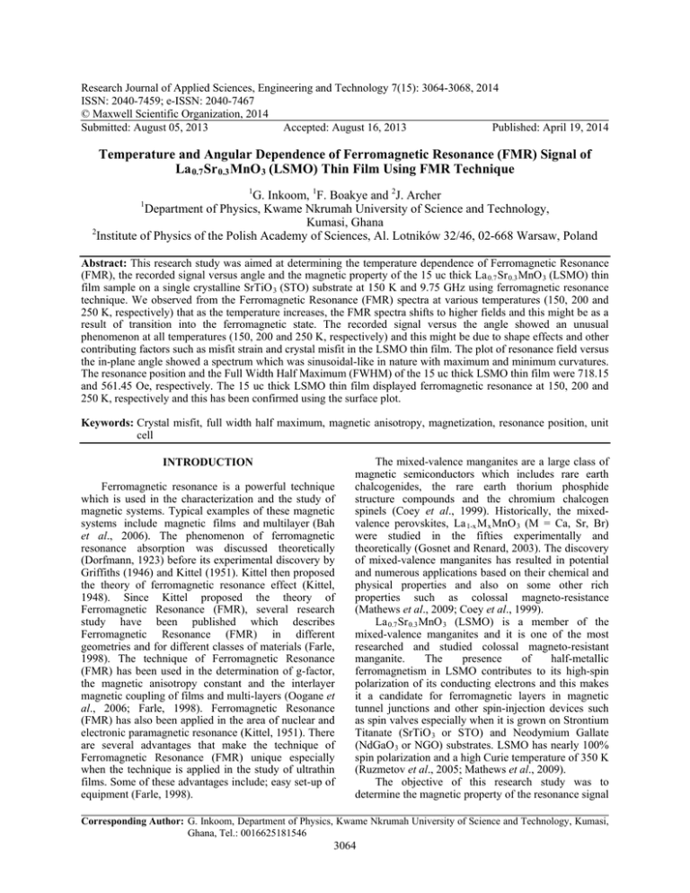
Research Journal of Applied Sciences, Engineering and Technology 7(15): 3064-3068, 2014 ISSN: 2040-7459; e-ISSN: 2040-7467 © Maxwell Scientific Organization, 2014 Submitted: August 05, 2013 Accepted: August 16, 2013 Published: April 19, 2014 Temperature and Angular Dependence of Ferromagnetic Resonance (FMR) Signal of La 0.7 Sr 0.3 MnO 3 (LSMO) Thin Film Using FMR Technique 1 G. Inkoom, 1F. Boakye and 2J. Archer Department of Physics, Kwame Nkrumah University of Science and Technology, Kumasi, Ghana 2 Institute of Physics of the Polish Academy of Sciences, Al. Lotników 32/46, 02-668 Warsaw, Poland 1 Abstract: This research study was aimed at determining the temperature dependence of Ferromagnetic Resonance (FMR), the recorded signal versus angle and the magnetic property of the 15 uc thick La 0.7 Sr 0.3 MnO 3 (LSMO) thin film sample on a single crystalline SrTiO 3 (STO) substrate at 150 K and 9.75 GHz using ferromagnetic resonance technique. We observed from the Ferromagnetic Resonance (FMR) spectra at various temperatures (150, 200 and 250 K, respectively) that as the temperature increases, the FMR spectra shifts to higher fields and this might be as a result of transition into the ferromagnetic state. The recorded signal versus the angle showed an unusual phenomenon at all temperatures (150, 200 and 250 K, respectively) and this might be due to shape effects and other contributing factors such as misfit strain and crystal misfit in the LSMO thin film. The plot of resonance field versus the in-plane angle showed a spectrum which was sinusoidal-like in nature with maximum and minimum curvatures. The resonance position and the Full Width Half Maximum (FWHM) of the 15 uc thick LSMO thin film were 718.15 and 561.45 Oe, respectively. The 15 uc thick LSMO thin film displayed ferromagnetic resonance at 150, 200 and 250 K, respectively and this has been confirmed using the surface plot. Keywords: Crystal misfit, full width half maximum, magnetic anisotropy, magnetization, resonance position, unit cell INTRODUCTION Ferromagnetic resonance is a powerful technique which is used in the characterization and the study of magnetic systems. Typical examples of these magnetic systems include magnetic films and multilayer (Bah et al., 2006). The phenomenon of ferromagnetic resonance absorption was discussed theoretically (Dorfmann, 1923) before its experimental discovery by Griffiths (1946) and Kittel (1951). Kittel then proposed the theory of ferromagnetic resonance effect (Kittel, 1948). Since Kittel proposed the theory of Ferromagnetic Resonance (FMR), several research study have been published which describes Ferromagnetic Resonance (FMR) in different geometries and for different classes of materials (Farle, 1998). The technique of Ferromagnetic Resonance (FMR) has been used in the determination of g-factor, the magnetic anisotropy constant and the interlayer magnetic coupling of films and multi-layers (Oogane et al., 2006; Farle, 1998). Ferromagnetic Resonance (FMR) has also been applied in the area of nuclear and electronic paramagnetic resonance (Kittel, 1951). There are several advantages that make the technique of Ferromagnetic Resonance (FMR) unique especially when the technique is applied in the study of ultrathin films. Some of these advantages include; easy set-up of equipment (Farle, 1998). The mixed-valence manganites are a large class of magnetic semiconductors which includes rare earth chalcogenides, the rare earth thorium phosphide structure compounds and the chromium chalcogen spinels (Coey et al., 1999). Historically, the mixedvalence perovskites, La 1-x M x MnO 3 (M = Ca, Sr, Br) were studied in the fifties experimentally and theoretically (Gosnet and Renard, 2003). The discovery of mixed-valence manganites has resulted in potential and numerous applications based on their chemical and physical properties and also on some other rich properties such as colossal magneto-resistance (Mathews et al., 2009; Coey et al., 1999). La 0.7 Sr 0.3 MnO 3 (LSMO) is a member of the mixed-valence manganites and it is one of the most researched and studied colossal magneto-resistant manganite. The presence of half-metallic ferromagnetism in LSMO contributes to its high-spin polarization of its conducting electrons and this makes it a candidate for ferromagnetic layers in magnetic tunnel junctions and other spin-injection devices such as spin valves especially when it is grown on Strontium Titanate (SrTiO 3 or STO) and Neodymium Gallate (NdGaO 3 or NGO) substrates. LSMO has nearly 100% spin polarization and a high Curie temperature of 350 K (Ruzmetov et al., 2005; Mathews et al., 2009). The objective of this research study was to determine the magnetic property of the resonance signal Corresponding Author: G. Inkoom, Department of Physics, Kwame Nkrumah University of Science and Technology, Kumasi, Ghana, Tel.: 0016625181546 3064 Res. J. Appl. Sci. Eng. Technol., 7(15): 3064-3068, 2014 of a 15 unit cell (uc) thick La 0.7 Sr 0.3 MnO 3 (LSMO) thin film sample at 150 K and 9.75 GHz which was fabricated by the Pulsed Laser Deposition technique (PLD) on SrTiO 3 (STO) substrate. The temperature dependence of FMR spectra of the 15 uc thick LSMO thin film was also investigated. Finally, the angular dependence of the FMR signal was also studied. 150 Recorded Signal [arb.unit] 100 METHODOLOGY 0 -50 -100 500 700 600 900 800 Magnetic field[Oe] 1000 1100 1200 Fig. 1: Recorded signal versus Field/Oe (FMR spectra) for the 15 uc LSMO thin film sample at 200 K and 9.75 GHz 80 60 Recorded Signal [arb.unit] La 0.7 Sr 0.3 MnO 3 (LSMO) thin film of different unit cells thicknesses were fabricated using the pulsed laser deposition technique (KrF excimer, λ = 248 nm) with a pulse energy density of 1-2J/cm3 on (001) SrTiO 3 substrate. The films were deposited at a substrate temperature of 700-800°C, keeping the oxygen pressure within 200-400 mTorr. The thin films were cut into smaller dimensions of 1×1 mm2 pieces using 503 nm Nd: YAG wavelength laser. This was done in order to keep the resonance value of the quality factor. Ferromagnetic resonance measurements were carried out with a Bruker ElexSys E500 EPR spectrometer using an X-band frequency of 9.75 GHz microwave source and a TE 102 model cavity. In this Bruker ElexSys E500 EPR spectrometer, the applied dc magnetic field was in the horizontal plane and the microwave magnetic field was vertical. In a situation where the direction of the external magnetic field is produced by a positive current which moves in a coil this is given by the right-hand rule. Ferromagnetic resonance measurement was carried out on the 15 unit cell (uc) thick La 0.7 Sr 0.3 MnO 3 (LSMO) thin film. This was done by positioning the 15 uc thick LSMO thin film in a particular orientation (110) in the quartz sample holder. The quartz sample holder which contains the LSMO thin film was inserted into the microwave cavity of the ElexSys E500 EPR spectrometer for angular dependence of FMR spectrum to be recorded on the computer. This was achieved by rotating the sample holder which contains the LSMO thin film with a goniometer which was mounted on top of the microwave cavity of the Bruker ElexSys E500 EPR spectrometer. Electromagnet was used in supplying magnetic field to the LSMO thin film. The applied dc magnetic field was swept through the LSMO sample in the microwave cavity till resonance was achieved. At resonance, the power which is absorbed by the LSMO thin film was maximum. The FMR spectra which were observed at a frequency of 9.75 GHz, with a power of 0.6325 mW, tolerance of 1.00 K, modulation frequency of 100.00 kHz, modulation amplitude of 10.00 AM and power attenuation of 25.0 dB were recorded on the personal computer. In order to avoid contaminating the microwave cavity of the Bruker ElexSys E500 spectrometer with paramagnetic contaminants which produces spurious EPR signals, the quartz sample holder was consistently wiped with a 50 40 20 0 -20 -40 -60 500 550 600 650 700 750 800 Magnetic field[Oe] 850 900 950 Fig. 2: Recorded signal versus Field/Oe (FMR spectra) for the 15 uc LSMO thin film sample at 250 K and 9.75 GHz clean tissue paper. Angular dependence of FMR spectra were recorded with the magnetic field rotated in the film plane (i.e., magnetic field is applied parallel to the thin film). RESULTS AND DISCUSSION The recorded signal versus the field for the 15 uc LSMO thin film sample at 200 and 250 K is as shown in Fig. 1 and 2. As it can be observed in Fig. 1 and 2, the base line is at the zero-mark and this quiet significant. Figure 1 and 2 shows that FMR phenomenon occurred in the 15 uc LSMO thin film at 200 and 250 K. Figure 3 shows the plot of the resonance field versus the in-plane angle for the 15 uc thick LSMO thin film sample at 150 K. According to Kwon et al. (2011) the presence of in-plane ferromagnetic resonance in 3065 Res. J. Appl. Sci. Eng. Technol., 7(15): 3064-3068, 2014 -0.5 -1 Recorded Signal -1.5 -2 -2.5 -3 -3.5 Fig. 3: Resonance field/Oe versus in-plane angle/deg of the 15 uc LSMO thin film sample at 150 K and 9.75 GHz 0 20 40 60 80 100 Angle/deg 120 140 160 180 Fig. 5: Recorded signal versus angle/deg of the 15 uc LSMO thin film at 150 K 0.1 800 150K 0 200K 600 400 -0.1 250K Recorded Signal Recorded signal 200 0 -200 -0.2 -0.3 -0.4 -400 -0.5 -600 -0.6 -800 -1000 400 -0.7 600 800 1000 1400 1200 Field/Oe 1600 1800 2000 2200 Fig. 4: Recorded signal versus Field/Oe (FMR spectra) at different temperatures (150, 200 and 250 K, respectively) and 9.75 GHz for the 15 uc LSMO thin film sample LSMO can be attributed to the distribution of anisotropies in the thin film. Also, this in-plane angular dependence of the resonance field might be attributed to unidirectional and uniaxial anisotropies in the LSMO thin film. As shown in Fig. 3, the resonance spectrum evolves as the field is rotated in the in-plane orientation. Clearly, the resonance spectrum is sinusoidal-like in nature and this is consistent with earlier research work which was conducted on LSMO bi-crystalline thin film sample at 150 K and 9.5 GHz on STO substrate (Alejandro et al., 2010). The resonance position of the 15 uc LSMO thin film sample from Fig. 3 was 718.15 Oe and the Full Width Half Maximum (FWHM) was 561.45 Oe. The resonance position in Fig. 3 might be as a result of the in-plane anisotropy and the resonance width might be attributed to disorder in the LSMO thin film (Beaujour et al., 2009). This disorder is as a result of two main factors. First, fluctuations in magnetic properties of the material such as magnetization and 0 20 40 60 100 80 Angle/deg 120 140 160 180 Fig. 6: Recorded signal versus angle/deg of the 15 uc LSMO thin film at 200 K second as a result of the fact that in a typical ferromagnetic resonance experiment, uniform precessional mode (K = 0) are excited and this generate finite-K (K ≠ 0) (Beaujour et al., 2009). Typical experimental spectra of the 15 uc LSMO thin film at different temperatures is as shown in Fig. 4. These temperatures were 150, 200 and 250 K, respectively. It can be observed from the FMR spectra in Fig. 4 that as the temperature increases, the ferromagnetic resonance spectra shifts to higher fields and this might be as a result of the transition into ferromagnetic state. This is consistent with the studies of Tovstolytkin et al. (2004) when FMR measurements where performed on LSMO thin film at temperature range of 77 to 300 K using a RADIOPAN spectrometer which operates at 9.2 GHz. We also observed from Fig. 4 that the signal intensity decreases with increasing temperature and this might be due to decrease in magnetization. This result is in agreement with Pradhan et al. (2006) and Farle et al. (2000). Figure 5 to 7 show the plot of the recorded signal versus angle at 150, 200 and 250 K, respectively. Clearly, the plots of the recorded signal versus angle 3066 Res. J. Appl. Sci. Eng. Technol., 7(15): 3064-3068, 2014 -0.2 Recorded Signal -0.25 -0.3 -0.35 -0.4 -0.45 0 20 40 60 80 100 Angle/deg 120 140 160 180 Fig. 7: Recorded signal versus angle/deg of the 15 uc LSMO thin films at 250 K Fig. 10: Surface plot of 15 uc LSMO thin film at 200 K and at 9.75 GHz 0.1 0 Recorded Signal -0.1 200K 250K -0.2 -0.3 -0.4 -0.5 -0.6 -0.7 0 20 40 60 80 100 Angle/deg 120 140 160 180 Fig. 8: Recorded signal versus angle/deg of the 15 uc LSMO thin film at 200 and 250 K Fig. 11: Surface plot of 15 uc LSMO thin film at 250 K and at 9.75 GHz 0.5 200K 250K 0 -0.5 Recorded Signal 150K -1 -1.5 -2 -2.5 -3 -3.5 0 20 40 60 80 100 Angle/deg 120 140 160 180 Fig. 9: Recorded signal versus angle/deg of the 15 uc LSMO thin film at 150, 200 and 250 K, respectively shows an unusual phenomenon and this might be as a result of shape effects and different residual stress in the LSMO thin film (Pradhan et al., 2006). Apart from the above mentioned factors which might have caused such an unusual phenomenon in the 15 uc LSMO thin film, thermal expansion coefficient mismatch between the Substrate (STO) and the thin film (LSMO) and Fig. 12: Surface plot of 15 uc LSMO thin film at 150 K and at 9.75 GHz misfitstrain might have also contributed to it. Generally, when LSMO thin film is fabricated on STO substrate, due to thermal expansion coefficient mismatch; it generates a crystal misfit which is less than 1% for all temperatures below 1000 K (Fang and Lo, 2000). 3067 Res. J. Appl. Sci. Eng. Technol., 7(15): 3064-3068, 2014 Figure 8 and 9 also shows the plot of the recorded signal versus angle at various temperatures (150, 200 and 250 K, respectively). These figures indeed also confirm to the fact that the recorded signal versus angle at various temperatures reveals an unusual phenomena. Figure 10 to 12 confirms ferromagnetic resonance phenomenon for the 15 uc thick LSMO thin film at 150, 200 and 250 K, respectively using surface plot. CONCLUSION The temperature dependence of the Ferromagnetic Resonance (FMR) spectra and the recorded signal versus angle of the 15 uc La 0.7 Sr 0.3 MnO 3 (LSMO) thin film on SrTiO 3 (STO) substrate have been studied using FMR technique. The resonance position and the Full Width Half Maximum (FWHM) of the 15 uc LSMO thin film were 718.15 and 561.45 Oe, respectively. The resonance field versus the in-plane angle was sinusoidal-like in nature as expected. The plot of the recorded signal versus the field at various temperatures (150, 200 and 250 K, respectively) revealed that as the temperature increases, the ferromagnetic resonance spectra shifts to higher fields. We also observed that the signal intensity decreases with increasing temperature. Finally, it has been established that the recorded signal versus angle of the 15 uc LSMO thin film at 150, 200 and 250 K, respectively showed an unusual phenomenon. ACKNOWLEDGMENT The authors would like to acknowledge the Department of Physics, Norwegian University of Science and Technology, Norway and the Norwegian Government through the Quota Scheme Scholarship where this study was done and sponsored respectively. The authors would also like to thank Asmund Monsen (Ph.D) for his advice and technical assistance. REFERENCES Alejandro, G., L.B. Steren, H. Pastoriza, D. Vega, M. Granada, J.C. Sanchez Rojas, M. Sirena and B. Alascio, 2010. Magnetoresistance effect in (La, Sr) MnO 3 bicrystalline films. J. Phys-Condens. Mat., 22: 1-11. Bah, R., D. Bitok, R.R. Rakhimov and M.M. Noginova, 2006. Ferromagnetic resonance studies on colossal magnetoresistance film: Effects of homogeneity and light illumination. J. Appl. Phys., 99(8): 08Q312-08Q312-3. Beaujour, J.M., D. Ravelosona, I. Tudosa, E. Fullerton and A.D. Kent, 2009. Ferromagnetic resonance linewidth in ultrathin films with perpendicular magnetic anisotropy. Phys. Rev. B, 80: 180415. Coey, J.M.D, M. Viret and S. Von Molnar, 1999. Mixed-valence manganites. Adv. Phys., 48(2): 167-293. Fang, W. and C.Y. Lo, 2000. On the thermal expansion coefficient of thin films. Sensors Actuator., 82: 310-314. Farle, M., 1998. Ferromagnetic resonance of ultrathin metallic layers. Rep. Prog. Phys., 61: 755-826. Farle, M., J. Lindner and K. Baberschke, 2000. Ferromagnetic resonance of Ni (111) and Re (0001). J. Magn. Magn. Mater., 212: 301-306. Gosnet, A.M.H. and J.P. Renard, 2003. CMR manganites: Physics, thin films and devices. J. Phys. Appl. Phys., 36: R127-R150. Griffiths, J.H.E., 1946. Nature, 158: 670. Kittel, C., 1948. On the theory of ferromagnetic resonance absorption. Phys. Rev., 73(2): 155-161. Kittel, C., 1951. Ferromagnetic resonance. J. Phys. Radium, 2: 291-302. Mathews, M., R. Jansen, G.R. Rijnders, J.C. Lodder and D.H.A. Blank, 2009. Magnetic oxide nanowires with strain-controlled uniaxial magnetic anisotropy direction. Phys. Rev. B, 80: 1-7. Oogane, M., T. Wakitani, S. Yakata, R. Yilgin, Y. Ando, A. Sakuma and T. Miyazaki, 2006. Magnetic damping in ferromagnetic thin films. Japanese J. Appl. Phys., 45(5A): 3889-3891. Pradhan, A.K., J.B. Dadson, D. Hunter, K. Zhang, S. Mohanty, E.M. Jackson, B. Lasley-Hunter, K. Lord, T.M. Williams, B.R. Sekhar, U.N. Roy, Y. Cui and A. Burger, 2006. Ferromagnetic properties of epitaxial manganite films on SrTiO 3 / Si heterostructures. J. Appl. Phys., 100: 3-7. Ruzmetov, D., Y. Seo, L.J. Belenky, D.M. Kim, X. Ke, S. Haipin, V. Chandrasekhar, C.B. Eom, M.S. Rzchowski and X. Pan, 2005. Epitaxial magnetic perovskite nanostructures. Adv. Mater., 17(23): 2869-2872. Tovstolytkin, A., A. Pogorily, A. Vovk, D. Podyalovskii, I. Lezhnenko and A. Matviyenko, 2004. Magnetoresistance and phase separation in thin films of moderately Sr-doped manganites. J. Magn. Magn. Mater., 272: 1839-1840. 3068
