TDMA Synchronization Using PIC Micro- controller and Balanced Modulator
advertisement

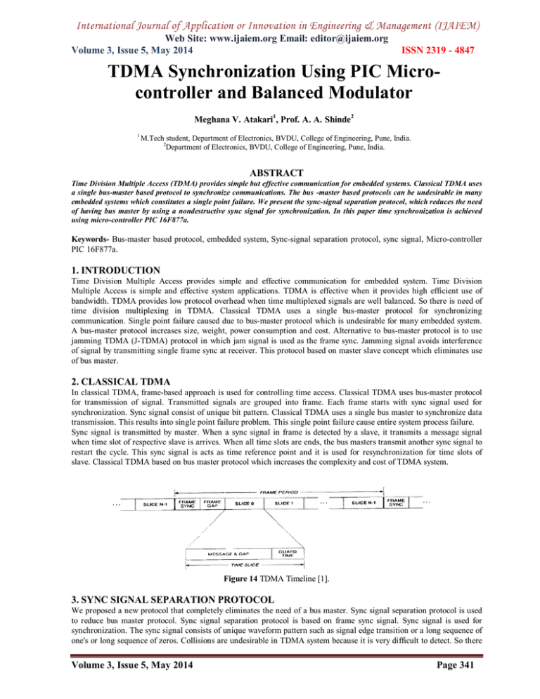
International Journal of Application or Innovation in Engineering & Management (IJAIEM) Web Site: www.ijaiem.org Email: editor@ijaiem.org Volume 3, Issue 5, May 2014 ISSN 2319 - 4847 TDMA Synchronization Using PIC Microcontroller and Balanced Modulator Meghana V. Atakari1, Prof. A. A. Shinde2 1 M.Tech student, Department of Electronics, BVDU, College of Engineering, Pune, India. 2 Department of Electronics, BVDU, College of Engineering, Pune, India. ABSTRACT Time Division Multiple Access (TDMA) provides simple but effective communication for embedded systems. Classical TDMA uses a single bus-master based protocol to synchronize communications. The bus -master based protocols can be undesirable in many embedded systems which constitutes a single point failure. We present the sync-signal separation protocol, which reduces the need of having bus master by using a nondestructive sync signal for synchronization. In this paper time synchronization is achieved using micro-controller PIC 16F877a. Keywords- Bus-master based protocol, embedded system, Sync-signal separation protocol, sync signal, Micro-controller PIC 16F877a. 1. INTRODUCTION Time Division Multiple Access provides simple and effective communication for embedded system. Time Division Multiple Access is simple and effective system applications. TDMA is effective when it provides high efficient use of bandwidth. TDMA provides low protocol overhead when time multiplexed signals are well balanced. So there is need of time division multiplexing in TDMA. Classical TDMA uses a single bus-master protocol for synchronizing communication. Single point failure caused due to bus-master protocol which is undesirable for many embedded system. A bus-master protocol increases size, weight, power consumption and cost. Alternative to bus-master protocol is to use jamming TDMA (J-TDMA) protocol in which jam signal is used as the frame sync. Jamming signal avoids interference of signal by transmitting single frame sync at receiver. This protocol based on master slave concept which eliminates use of bus master. 2. CLASSICAL TDMA In classical TDMA, frame-based approach is used for controlling time access. Classical TDMA uses bus-master protocol for transmission of signal. Transmitted signals are grouped into frame. Each frame starts with sync signal used for synchronization. Sync signal consist of unique bit pattern. Classical TDMA uses a single bus master to synchronize data transmission. This results into single point failure problem. This single point failure cause entire system process failure. Sync signal is transmitted by master. When a sync signal in frame is detected by a slave, it transmits a message signal when time slot of respective slave is arrives. When all time slots are ends, the bus masters transmit another sync signal to restart the cycle. This sync signal is acts as time reference point and it is used for resynchronization for time slots of slave. Classical TDMA based on bus master protocol which increases the complexity and cost of TDMA system. Figure 14 TDMA Timeline [1]. 3. SYNC SIGNAL SEPARATION PROTOCOL We proposed a new protocol that completely eliminates the need of a bus master. Sync signal separation protocol is used to reduce bus master protocol. Sync signal separation protocol is based on frame sync signal. Sync signal is used for synchronization. The sync signal consists of unique waveform pattern such as signal edge transition or a long sequence of one's or long sequence of zeros. Collisions are undesirable in TDMA system because it is very difficult to detect. So there Volume 3, Issue 5, May 2014 Page 341 International Journal of Application or Innovation in Engineering & Management (IJAIEM) Web Site: www.ijaiem.org Email: editor@ijaiem.org Volume 3, Issue 5, May 2014 ISSN 2319 - 4847 is a necessity of transmission of sync signal along with signals. Any signal which propagates along with transmission data without causing any interference or destruction is called as "sync signal". In this paper, Sync signal consists of sequences of zeros. Sequences of zeros represented as sync signal which is used for synchronization. The key idea of sync signal separation protocol is to use a nondestructive sync signal for synchronization. The sync signal is used to avoid interference of signals. Sync signal propagate along with signal without causing distortion. Sync signal does not contain any data. In synchronization, it is essential to detect sync signal to established communication. Detection of sync signal is easier than detection of collision because nondestructive waveform is transmitted along with data.PIC 16F877a is used for synchronization purpose. Time division multiplexing is used to reduce protocol overhead. Micro-controller PIC 16F877a is used to apply control signal for multiplexing. On the application of control signal respective signal get selected for that time slot. When control signals are applied as "11" sync signal is selected which is sequence of zeros. Similarly at the receiver side micro-controller is used for de-multiplexing. 4. PROPOSED METHOD Here, time division multiplexing is achieved using CD 4051. CD 4051 is 8 channel analog multiplexer / de-multiplexer with three binary control inputs. Micro-controller PIC 16F877a is used to provide control signal to multiplexer CD 4051. Sine wave, square wave and triangular wave applied as inputs to multiplexer. When control lines from micro-controller are applied according to that signal get selected at output. When status of control lines is "00" square wave, "01"triangular wave,"10"sine wave and "11"sync signal is selected respectively at the output. Time multiplexed data is then modulated using amplitude modulation so that all signals can use same carrier frequency for transmission. For modulation carrier wave of 2 KHz frequency is used. port B of micro-controller is used. TRISB is used for selection of port as input or output port. When TRISB is 0X00 it is acts as output port and when TRISB is 0XFF it is used as input port. In this paper, TRISB is used as output port so it is set as 0X00. Similarly at receiver side for de-multiplexing micro-controller is used. Figure 15 Simulation of multiplexer with micro-controller using proteus Figure 16 Flow-chart for Synchronization Volume 3, Issue 5, May 2014 Page 342 International Journal of Application or Innovation in Engineering & Management (IJAIEM) Web Site: www.ijaiem.org Email: editor@ijaiem.org Volume 3, Issue 5, May 2014 ISSN 2319 - 4847 5. RESULTS Figure 17 Time Division Multiplexing using PIC 16F877a Figure 5 Sync signal multiplexing using 16f877a Figure 6 Modulated triangular waves Volume 3, Issue 5, May 2014 Page 343 International Journal of Application or Innovation in Engineering & Management (IJAIEM) Web Site: www.ijaiem.org Email: editor@ijaiem.org Volume 3, Issue 5, May 2014 ISSN 2319 - 4847 Figure 7 Modulated square waves Figure 8 Modulated sine waves Figure 9 Modulated sync waves Volume 3, Issue 5, May 2014 Page 344 International Journal of Application or Innovation in Engineering & Management (IJAIEM) Web Site: www.ijaiem.org Email: editor@ijaiem.org Volume 3, Issue 5, May 2014 ISSN 2319 - 4847 6. CONCLUSION This paper gives introduction to new communication protocol, which is sync signal separation protocol. By using sync signal, transmission of data without interference is achieved. Protocol overhead is reduced using time division multiplexing. System design is simulated using proteus software and also tested the results on CRO. REFERENCES [1] Time Division Multiple Access without bus master by Philip J. Koopman, Bhargav P. Upender http://users.ece.cmu.edu/~koopman/networks/koopman95_tdma.pdf [2] U.S.Patent on frame timing control of time division multiple access [3] http://books.google.co.in/books?id=QUuQdLDUtSoC&lpg=PA81&ots=lXrAHt9AmV&dq=synchronisation%20i n%20tdma%20using%20microcontroller&pg=PA80#v=onepage&q=synchronisation%20in%20tdma%20using%20m icrocontroller&f=false [4] http://books.google.co.in/books?id=6FOPbhbYeMC&pg=PT177&lpg=PT177&dq=tdma+synchronisation+concept+u sing+microcontroller&source=bl&ots=9N4QsYuf0&sig=HpnCMPcyneh6sJUBYUfSwmvGiwc&hl=en&sa=X&ei=yF QuU5eADoWTrgftp4CYBQ&ved=0CCYQ6AEwAA#v=onepage&q=tdma%20synchronisation%20concept%20using %20microcontroller&f=false. Volume 3, Issue 5, May 2014 Page 345


