Urban Search and Rescue Robotics | Tele-Operated Robot
advertisement

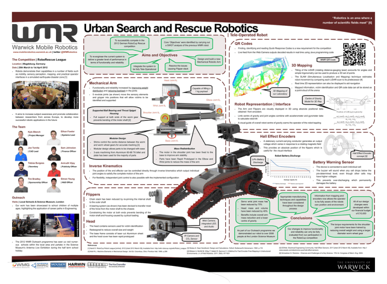
“Robotics is an area where a number of scientific fields meet” [6] Urban Search and Rescue Robotics | Tele-Operated Robot To successfully compete in the 2012 German RoboCup Rescue competition www.mobilerobotics.warwick.ac.uk | twitter @WMRobotics Location | Magdeburg, Germany Robots demonstrate their capabilities in a number of fields such as mobility, sensory perception, mapping, and practical operator interfaces in a simulated earthquake disaster zone [1] Finding, identifying and reading Quick Response Codes is a new requirement for the competition Live feed from the Web Camera outputs decoded results in real time using Java programming code WMR QR Code 3D Mapping Resolve the issues causing Flipper slack Head Joint θ5 Mechanical Arm Functionality and reliability increased by improving weight distribution and reducing backlash in the joints | 2011 RoboRescue Competition QR Codes Design and build a new Mechanical Robotic Arm Integrate the system to be fully Tele-Operational Date | 28th March to 1st April 2012 Aims and Objectives To re-engineer the current system to deliver a greater level of performance in terms of functionality and reliability The Competition | RoboRescue League Core ‘Objectives’ were identified by carrying out a SWOT analysis of the previous WMR robot 5 revolute joints (as shown) move the sensory elements and gripper into positions that will allow victims to be identified and supported It aims to increase subject awareness and promote collaboration between researchers from across Europe, to develop more successful robotic applications in the future 3D Mapping of our Laboratory The SLAM (Simultaneous Localisation and Mapping) technique estimates robot movement by comparing each LiDAR scan to its predecessor [4] Real time 2D representation can also be displayed to aid navigation Mapped information, victim identification and QR code data can all be stored as a point-cloud of the arena Centre of Gravity Model for 3D Rep. Elbow Joint θ3 Robot Representation | Interface Wrist Joint θ4 Supported Ball Bearing and Thrust Spigot Housing Capable of lifting a 1 kg payload Tilting of the LiDAR (rotating distance-gauging laser) accounts for angles and simple trigonometry can be used to produce a 3D set of points Shoulder Joint θ2 Full support at both ends of the worm gear prevents bending of the motor shaft [2] The Arm and Flippers are visually displayed in 3D using absolute positional data obtained from encoders Limb centre of gravity and joint angles combine with accelerometer and gyrometer data to calculate robot tilt A visual guide of overall robot centre of gravity warns the operator of the robot toppling The Team Kyle Blanch Ethan Fowler | Project Manager | Systems Lead Hall Effect Encoders Modular Design | CAD Lead | Finance Officer 3-axis machining from Aluminium 60-68 T6 billet and plate has been used for the majority of parts Tobias Burgess Anirudh Vijay | Secretary | Publicity Officer Simon Yeung | Sponsorship Officer | H&S Officer Parts have been Rapid Prototyped in the Elbow and Wrist joints to reduce the mass of the arm LiPo Battery Discharge The position of the end effector can be controlled directly through inverse kinematics which output individual joint angles to satisfy the complete motion of the arm 4.3 4.1 3.9 3.7 3.5 3.3 3.1 2.9 2.7 2.5 Battery Warning Sensor For flexibility, independent joint control is also possible with the implemented configuration Flippers Our work has been showcased to school children of multiple ages, highlighting the application of career paths in Engineering | Science Museum | School Visit The 2012 WMR Outreach programme has seen us visit numerous schools within the local area and partake in the Science Museum’s Antenna Live Exhibition during the half term school holiday Chain slack has been reduced by re-pinning the internal shaft to the outer shaft A bearing system (as shown) has been devised to transfer most of the force from the motor shaft to the chassis Constraining the motor at both ends prevents bending of the motor shaft and housing caused by cyclical loading Head The head contains sensors used for victim identification Redesigned to reduce overall size and weight The base frame consists of laser cut Aluminium sheet and the hood cover has been rapid prototyped Hall Effect Encoder concept [5] Robot Battery Discharge Battery Discharge Visits | Local Schools & Science Museum, London This provides an absolute position of the flippers which is useful for the visual interface Discharge Capacity (%) Outreach The motor in the shoulder joint has been fixed to the base to improve arm stability Inverse Kinematics Tim Bradley Mass Redistribution Modular design allows parts to be changed with ease A stationary current-carrying conductor generates an output voltage which varies in response to a rotating magnetic field 0 5 10 15 20 25 30 35 40 45 50 55 60 65 70 75 80 85 90 95 100 Sam Johnston Voltage (V) Joe Tomita Base Joint θ1 Shims control the centre distance between the worm and worm wheel gears for accurate meshing [3] Web Camera, integrated LED, and Audio IR Camera and CO2 Sensor Servo wrist joint mass has been reduced by 75% Head mass and volume have been reduced by 45% Benefits include overall arm mass reduction and a lower centre of gravity As part of our Outreach programme we demonstrated our robot to over 2000 people at the London Science Museum Battery warning level Appropriate manufacturing techniques and capabilities have been considered throughout the design process The device is connected to each individual cell The buzzer will sound when any cell drops below the pre-determined level, even though other cells may have higher voltages This prevents over-discharging damages the battery Information from mapping and encoders now allows the operator to be fully aware of the robots own position and environment which permanently All of our design changes were developed within our financial budget of £10,000 Conclusions Our changes to improve functionality and reliability can only be fully evaluated from our participation in the RoboCup competition The torque requirements for the shoulder joint motor have been halved by reducing overall weight and using a larger diameter worm wheel gear References [1] Nardi D. RoboCup Robot League [online]. 2012 [cited 2012 March 06]. Available from: http://wiki.robocup.org/wiki/Robot_League [3] Stokes A. Gear Handbook: Design and Calculations. Oxford: Butterworth-Heinemann; 1992. p.116 [2] Mott R.L. Machine Elements in Mechanical Design. 3rd Ed. Columbus, Ohio: Prentice Hall; 1999. p.296 TheViceChancellor The University of Warwick [4] Milstein A, McGill M, Wiley T, Salleh R, Sammut C. A Method for Fast Encoder-Free Mapping in Unstructured Environments. Jr. of Field Robotics. 2011. 28(6). 817-831 [5] EEWeb. Electrical Engineering Community: Hall Effect Sensors. 2011 [cited 2012 March 06]. Available from: http:// www.eeweb.com/electronics-quiz/hall-effect-sensors [6] Schweitzer G. Robotics - Chances and Challenges of a Key Science. 17th Int. Congress of Mech. Eng. 2003.


