Larger
advertisement
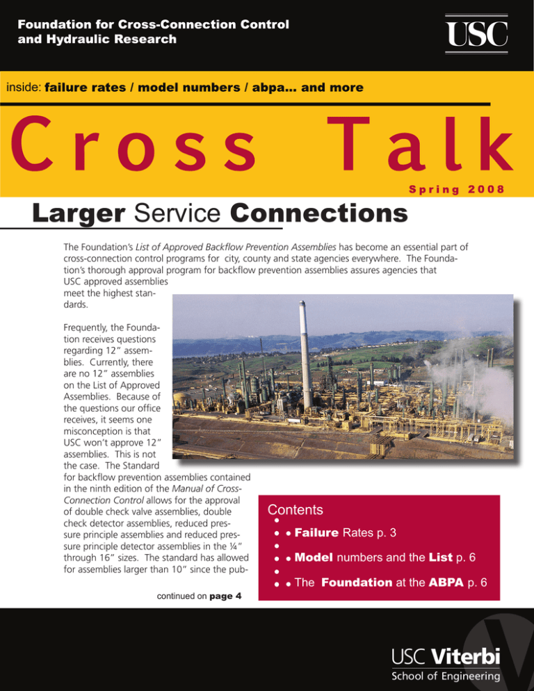
Larger Service Connections The Foundation’s List of Approved Backflow Prevention Assemblies has become an essential part of cross-connection control programs for city, county and state agencies everywhere. The Foundation’s thorough approval program for backflow prevention assemblies assures agencies that USC approved assemblies meet the highest standards. Frequently, the Foundation receives questions regarding 12” assemblies. Currently, there are no 12” assemblies on the List of Approved Assemblies. Because of the questions our office receives, it seems one misconception is that USC won’t approve 12” assemblies. This is not the case. The Standard for backflow prevention assemblies contained in the ninth edition of the Manual of CrossConnection Control allows for the approval of double check valve assemblies, double check detector assemblies, reduced pressure principle assemblies and reduced pressure principle detector assemblies in the ¼” through 16” sizes. The standard has allowed for assemblies larger than 10” since the pubcontinued on page 4 Contents Failure Rates p. 3 Model numbers and the List p. 6 The Foundation at the ABPA p. 6 Foundation Membership The Foundation’s Membership Program provides many benefits to the Members of the Foundation. These include: a twenty-five percent discount on manuals, twenty percent discount on Foundation Training Courses for any employee of the Member company/organization, the List of Approved Backflow Prevention Assemblies with access to the up-to-the-minute version on the Foundation’s website. Members are encouraged to call the Foundation with technical questions. The Foundation’s Engineering Staff is available to assist Members with the various aspects of field testing backflow preventers, installing backflow preventers and administering their cross-connection control program. Many consider their Membership with the Foundation one of their best forms of insurance to protect the agency from liability involved when a distribution system becomes contaminated or polluted through cross-connections. Membership in the Foundation helps to provide the tools needed to effectively initiate and run a cross-connection control program. Below is a list of those who have become members of the Foundation this past quarter: ABQ Cross-Connection Services Liberty Engineering, Inc. AJ’s Backflow Testing LLC. M & M Industrial Plumbing AZABPA M.J. Dillon & Associates American Water Macina, Bose, Copeland & Associates Archmetal Industries Corp. Mesquite MDWC & MSWA Axiom Engineering, Inc. Niking Corp. Big Island Mechanical LLC. Northern Fire Blue Sky Engineering, Inc. NxStage Medical, Inc. Brad Rea, P.E. Oceanic Companies Chapman University-Facilities Management Peabody Western Coal. Co. Eugene Water & Electric Board Russo Construction Company Eureka, City of Solvang, City of Fuscoe Engineering, Inc. USAutomatic Sprinkler Corp. Holaday-Parks, Inc. Your Neighborhood Plumbers, Inc. Cross Talk is published by the Foundation for Cross-Connection Control and Hydraulic Research at the University of Southern California for Foundation Members. Limited additional copies are available to Members upon request. 2008 © University of Southern California. All rights reserved. printed on Cross Talk SPRING 2008 Page 2 recycled paper Failure Rates Most administrative authorities require backflow prevention assemblies to be tested annually. Test results from these annual tests can be analyzed to determine the failure rate of backflow preventers. However, before failure rates are discussed it should be understood what is meant by “failure.” When a backflow preventer is said to fail, it means that the assembly failed to meet the field test criteria. It is important to understand that failure rates do not represent backflow assemblies that allow backflow to occur. The field test criteria for the double check valve assembly and the reduced pressure principle assembly are described below. Double Check Valve Assembly The field test for the double check valve assembly requires that each check valve holds at least 1.0 psid in the direction of flow. It is important to note that a check valve may fail the field test, but still prevent backflow. For example, if a double check valve assembly has test results of 0.5 psid for the first check valve and 0.7 psid for the second check valve, the assembly would fail the field test. Even though the assembly fails the test, the assembly is still preventing backflow. In fact, both check valves are holding, just not at the required level of 1.0 psid. Even if one of the checks leaked (having a value of 0.0 psid), this does not mean that the assembly fails to prevent backflow. As long as one of the check valves is holding, backflow will not occur through the assembly. In order for backflow to occur, both check valves would need to leak (have a value of 0.0 psid) and either a backpressure or backsiphonage condition must exist. Reduced Pressure Principle Assembly The reduced pressure principle assembly has three components that are tested during the field test. The relief valve is required to open at a value of at least 2 psid. The second check must hold tight, and the first check must hold at a value of at least 3.0 psid above the relief valve opening point. (Some jurisdictions vary on whether this 3.0 psid “buffer” is required.) Again, as with the DC, the RP can fail the field test, and yet still prevent backflow. The relief valve may not open, but as long as one of the check valves holds any value at all, backflow will not occur. Also, if both check valves leaked, but the relief valve worked properly, backflow would not occur. All of the components would have to fail and backpressure or backsiphonage would have to be present for backflow to occur. Reduced Pressure Principle Assembly with leaky relief valve The Manual Review Committee was provided with 18,000 field test(s) by various administrative authorities. The data showed between 0.5% and 25% of the assemblies tested failed to meet field test criteria. On average 11% of the assemblies tested failed to pass the field test. Although the numbers might seem high to some it is important to note that assemblies that fail the field test will most likely not allow backflow. g Cross Talk SPRING 2008 Page 3 Large Service Connection: continued continued from page 1 lication of the fourth edition of the Manual in March, 1969. However, to date, no assembly has been approved in any size larger than the 10” size. New prototype assemblies are submitted to the Foundation each month, so it is certainly possible that 12” and larger assemblies may become approved in the future. But, until that time, parallel assemblies will need to be used if Foundation Approval is required for assemblies. If the need arises for a backflow preventer on a 12” inch line, it would be necessary to install smaller assemblies in parallel. However, adequate flow rates must be provided for. For example a 12” assembly is rated for 3000 gallons per minute (GPM) of flow, whereas a 6” assembly is rated for 1000 GPM. So three 6” assemblies would allow for the same flow as one 12” assembly. Since the 8” assembly is rated at 1600 GPM, two 8” assemblies in parallel would provide sufficient flow for a 12” line. Having two assemblies installed in parallel is helpful when it comes to testing and maintenance as well. One assembly can be tested and maintained while the other assembly continues to provide water to the customer. It must be noted that the amount of flow provided to the customer would be reduced when one of the assemblies is offline for testing and maintenance. If the facility requires large flows of water with- Cross Talk SPRING 2008 Page 4 out any disruption or reduction of flow, the parallel assemblies must be able to provide the full amount of water needed, even with one of the assemblies offline. In some cases the customer may require a certain amount of flow at specific times. In this case it may be possible to have a bypass assembly of a smaller size to provide minimal water service while the line size assembly is being tested and maintained. For example: a facility requires a 10” assembly because it may use up to 2300 GPM at times and it can never go with the water cut off completely. In this case it may be possible to provide a 2” bypass assembly to be used during the testing Assemblies in parallel and maintenance of the 10” assembly. This would work as long as the testing was performed at a time when the facility would be using no more than 160 GPM (the rated flow for a 2” assembly.) Until larger assemblies are approved, it will be necessary to install parallel installations in order to get the flow rate required by the 12” and larger lines. g RP: Maximum First Check Values A question arises periodically as to the maximum value allowed for the first check of the reduced pressure principle assembly. The field test procedures do not state a maximum acceptable value for the first check valve. Depending upon the model and size, one may get values as high as the mid teens (14-16 psid). the downstream side of the No. 2 shutoff valve. So, if a 4” assembly has a first check valve reading of 14 psid, it is too high. The second check should hold at a minimum of 1.0 psid, plus there are other losses through the assembly. So, the entire pressure loss across PSID (Pounds per Square Inch Differential When field testing the Head Loss vs. Flow Rate RP there are specific 15 acceptable values: the 14 relief valve must open at a value of 2.0 psid or greater, the second check must hold tight (if using the direction 10 of flow test, the second check must hold at 1.0 psid or greater), the first check should hold at 5 a value that is at least 3.0 psid greater than the relief valve opening point. This is the recommended value according 0 50 100 150 to the Manual of CrossGPM (Gallons per Minute) Connection Control. This may or may not be a requirement, dependThe pressure drop across an entire 4”RP may not exceed 14 psid . ing upon the jurisdiction. One jurisdiction may require the 3.0 psid bufthe assembly would be 15 psid plus the other fer, whereas another may just require that the losses through the assembly. This exceeds the first check hold above the relief valve opening maximum allowable pressure loss for a 4” RP point. assembly. If this is the case, there is likely a problem in the No. 1 check valve that would Although there is not a maximum value listed need to be repaired, since the first check in the field testing procedures. It is possible valve would not be designed to have such a for the first check to be holding at a value high pressure loss. that is too high to be acceptable. This can be determined based on the overall allowable If one happens to come across a high reading pressure loss for the specific size of RP. on a No. 1 check valve of an RP, one could follow the same procedure discussed above For example, Table 10-1 of the Manual of to determine if the first check value is too Cross-Connection Control shows that a 4” RP high. It will be necessary to consult Table has a maximum allowable pressure loss of 14 10.1 to determine the maximum allowable psid. This means that no more than fourteen pressure loss for the specific size of assempounds per square inch of pressure may be bly. If it is determined that the reading is too lost across the assembly beginning from the high, the assembly should be disassembled to upstream side of the No. 1 shutoff valve to determine what type of repair is needed. g Cross Talk SPRING 2008 Page 5 Model Numbers and the List With more backflow prevention assemblies entering the market, it can become difficult to tell between a Foundation approved and unapproved assembly. The Foundation’s List of Approved Assemblies is a resource tool used by many contractors and municipalities. As a reference tool it is important to understand what is and isn’t approved by the Foundation. assembly to be considered approved by the Foundation. It is also important to note that 2008 List of Approved Backflow Prevention Assemblies 08 May 2008 Supersedes All Prior Lists Foundation for Cross-Connection Control and Hydraulic Research Notice Orientation of Assemblies The original Certificate of Approval - identified by the Edition of the Manual and the Approved date shown below - is valid only if the original or renewal date shown hereon is within three (3) years of the current date. The responsibility to request a renewal of an Approval is that of each manufacturer. The Foundation retains the right of determining the extent of re-evaluation required before renewal is granted. Certificates of Approval are not recalled for the purpose of updating the effective date. This revision of date is only published via the current List of Approved Backflow Prevention Assemblies. Unless otherwise specified by the manufacturer all assemblies are to be installed on cold potable water applications - below 110oF. Also all of the assemblies listed are Approved for INDICATED ORIENTATION ONLY (please see the legend to the left). Use of spare parts other than those of the original manufacturer invalidates the Approval. The List of Approved Assemblies is printed annually in the first quarter of the year. Update notices are printed and sent to Members quarterly. The most recent changes to the List may be found on the Foundation’s website. The web version of the List is updated each time a change is made. When the manufacturer submits an assembly for Foundation approval, a model number is provided. If that assembly successfully passes the approval process that model number along with other manufacturer and orientation information, is included in the List. printed on recycled paper 2008 © University of Southern California Page 1 of 31 It is Foundation policy that the model number found on the backflow assembly must match entirely with the model number found on the List for the In May, the Foundation took part in the 24th Annual American Backflow Prevention Association Conference & Trade Show in Indianapolis, Indiana. This annual event attracts a variety of personnel from the backflow prevention industry and it is an excellent opportunity to meet some of the Foundation staff. We would like to thank those of you who came by the booth located in the exhibition area. It was a pleasure meeting many of you and answering your questions. The Foundation would like to remind our members that we are always available for assistance via phone or e-mail. The Foundation at the ABPA Cross Talk SPRING 2008 Page 6 the Manual of Cross-Connection Control, which contains the Standard for the backflow preventers states that any modification to any backflow assembly invalidates the Foundation approval. This is clearly stated in Section 10.1.1.6 of the Manual In order to ensure proper installations, all backflow prevention assemblies shall be delivered for installation completely assembled by the original manufacturer with all components as approved. Resilient seated shutoff valves and test cocks are considered integral parts of the assembly. Therefore, it is crucial to keep in mind that any slight variation between backflow assembly and the List calls into question the Foundation approval. The model numbers must match exactly; there are no exceptions. New Field Testing Instructional Video As the Manual of Cross-Connection Control, tenth edition closes in on being released, the Foundation staff is hard at work putting together its latest instructional video. Field Testing Backflow Preventers Instructional Video is currently in production and is taking into account the new standards set forth by the tenth edition. The instructional video will clearly demonstrate the field test procedures for the double check valve assembly, reduced pressure principal assembly, pressure vacuum breaker and the spill-resistant pressure vacuum breaker. The video will combine liveaction and computer animation to better the students understanding of the inner-workings of backflow assemblies. If you have any questions about the approval of a backflow prevention assembly we recommend you contact the Foundation via phone or e-mail. g The Foundation will be in attendance next year as the show moves to Colorado Springs, CO for the 25th ABPA Annual Conference & Trade Show. g For the first time ever the instructional video will be available in high definition Blu-ray disc. The format will provide a better visual experience along with new features not currently available on the DVD. For those interested a DVD version will be made available. A VHS version of the instruction video will not be available . Stay tuned to the Foundation website for a release date later this year. g Cross Talk SPRING 2008 Page 7 Training Courses Tester Course Los Angeles, CA 14-18 July 2008 Los Angeles, CA 6-10 October 2008 Redwood City, CA 3-7 November 2008 Los Angeles, CA 26-30 January 2009 Upcoming Events Inland Counties Backflow Group Annual Conference San Bernardino, CA 10 September 2008 ABPA Western Regional Backflow Conference Las Vegas, NV 22-23 September 2008 AWWA CA-NV Fall Conference Reno, NV 20-23 October 2008 Specialist Course Los Angeles, CA 28 July-1 August 2008 San Antonio, TX 11-15 August 2008 Los Angeles, CA 5-9 January 2009 Foundation for Cross-Connection Control and Hydraulic Research University of Southern California Kaprielian Hall 200 Los Angeles, California 90089-2531 Contact Information Phone: 866-545-6340 Fax: 213-740-8399 E-mail: fccchr@usc.edu Website: www.usc.edu/fccchr First Class US Postage PAID University of Southern California
