Document 12961123
advertisement
Five techniques are employed to minimize the time to develop the test
vectors used to test manufactured parts on an IC component tester.
, 2-# 71 "-+.$2(2(4$ "-+.32$0 (,#31207 2'$ !(*(27 2""$*$0 2$ 2'$ #$4$*-.+$,2 .0-"$11 %0-+ #$1(&, 2- + ,39
% "230$# . 02 (, 2(+$*7 + ,,$0 (1 , (+.-02 ,2 % "2-0 2
1 '$*+1%-0# 1712$+1 * !-0 2-07 -,$ -% 2'$ 2'(,&1 5$
#- (1 #$1(&, ,# #$4$*-. "'(.1 %-0 $0($1 5-0)12 2(-,1 +-,& 2'$ "2(4(2($1 .$0%-0+$# #30(,& 2'(1
#$4$*-.+$,2 (1 2'$ &$,$0 2(-, -% 1$0($1 -% 2$12 4$"2-01
" **$# -.$0 2(-, * 2$12 0$*$ 1$ 4$"2-01 5'("' 0$
31$# -, "-+.-,$,2 2$12$01 2- 4$0(%7 2'$ "-00$"2,$11 -% 2'$
+ ,3% "230$# . 021
2 27.(" **7 2 )$1 1(6 +-,2'1 2- &$,$0 2$ ,# 4$0(%7 -.$0 9
2(-, * 2$12 0$*$ 1$ 4$"2-01 (2' 2'$ 2$"',(/3$1 #$1"0(!$# (,
2'(1 02("*$ 5$ ' 4$ !$$, !*$ 2- 0$#3"$ 2'$ 2(+$ 1.$,2
"0$ 2(,& 2'$1$ 4$"2-01 2- %-30 +-,2'1
'$ %(, * .0-#3"2 -% -30 2$12 4$"2-0 #$4$*-.+$,2 .0-"$11 (1
1$2 -% 4$"2-01 *1- " **$# 2$12 . 22$0,1 2' 2 " , !$ *- #$#
-,2- 2$12$0 2- 4$0(%7 + ,3% "230$# . 021 '71(" * #$%$"21
2' 2 ..$ 0 -, + ,3% "230$# . 021 " , !$ 1- 4 0($# 2' 2 (2 (1
-%2$, (+.0 "2(" * 2- 207 2- #$2$"2 2'$+ #(0$"2*7 ,12$ # 32-9
+ 2(" 2$12 &$,$0 2(-, 5 4$%-0+ "0$ 2(-, ,# 4$0(%(" 2(-,
2--*1 0$ $+.*-7$# 2- #$ * 5(2' *-&(" * +-#$* -% .'71(" *
#$%$"2 5'("' (1 ),-5, 1 % 3*2 '$ +-12 5(#$*7 31$#
% 3*2 +-#$* (1 2'$ 123")9 2 % 3*2 (, 5'("' 2'$ (,.32 -0 2'$
-32.32 -% *-&(" $*$+$,2 (1 123") 2 *-&(" -0 -0 $6 +9
.*$ , -.$, 20 "$ 113+(,& .-1(2(4$ *-&(" +(&'2 $6'(!(2
(21$*% 1 123") 2 *-&(" "' 4$"2-0 2' 2 2$121 27.(" * !*-") -% ..*(" 2(-, *-&(" ' 1
2 *$ 12 25- . 021 ,$ . 02 (1 + #$ 3. -% # 2 ,#-0 (,9
1203"2(-,1 5'("' 0$ ..*($# 2- 2'$ (,.32 -% 2'$ "'(. '$
-2'$0 . 02 " **$# 8$6.$"2$# 0$13*21 (1 31$# %-0 "-+. 0(1-,
5(2' 2'$ "23 * -32.32 -% 2'$ ..*(" 2(-, *-&(" 2- #$2$"2 ,7
% 3*21
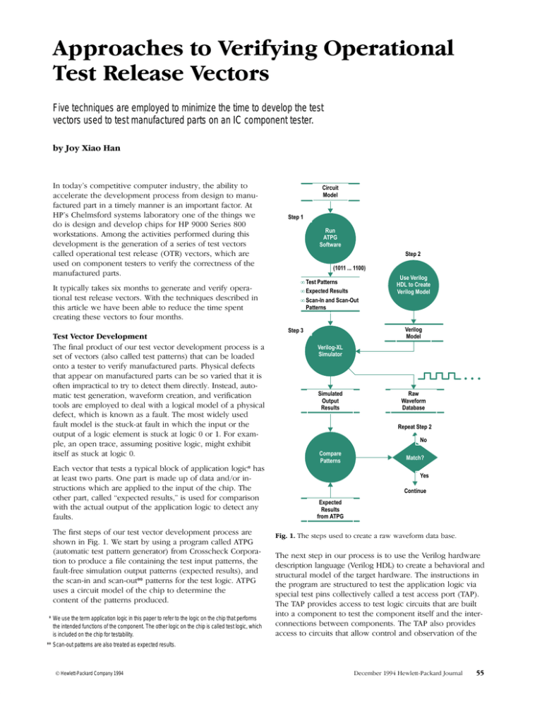
'$ %(012 12$.1 -% -30 2$12 4$"2-0 #$4$*-.+$,2 .0-"$11 0$
1'-5, (, (& $ 12 02 !7 31(,& .0-&0 + " **$# 32-+ 2(" 2$12 . 22$0, &$,$0 2-0 %0-+ 0-11"'$") -0.-0 9
2(-, 2- .0-#3"$ %(*$ "-,2 (,(,& 2'$ 2$12 (,.32 . 22$0,1 2'$
% 3*29%0$$ 1(+3* 2(-, -32.32 . 22$0,1 $6.$"2$# 0$13*21 ,#
2'$ 1" ,9(, ,# 1" ,9-32 . 22$0,1 %-0 2'$ 2$12 *-&(" 31$1 "(0"3(2 +-#$* -% 2'$ "'(. 2- #$2$0+(,$ 2'$
"-,2$,2 -% 2'$ . 22$0,1 .0-#3"$#
* We use the term application logic in this paper to refer to the logic on the chip that performs
the intended functions of the component. The other logic on the chip is called test logic, which
is included on the chip for testability.
Circuit
Model
Step 1
Run
ATPG
Software
Step 2
(1011 ... 1100)
• Test Patterns
• Expected Results
• Scan-In and Scan-Out
Patterns
Use Verilog
HDL to Create
Verilog Model
Verilog
Model
Step 3
Verilog-XL
Simulator
Simulated
Output
Results
Raw
Waveform
Database
Repeat Step 2
No
Compare
Patterns
Match?
Yes
Continue
Expected
Results
from ATPG
'$ 12$.1 31$# 2- "0$ 2$
0 5 5 4$%-0+ # 2 ! 1$
'$ ,$62 12$. (, -30 .0-"$11 (1 2- 31$ 2'$ $0(*-& ' 0#5 0$
#$1"0(.2(-, * ,&3 &$ $0(*-& 2- "0$ 2$ !$' 4(-0 * ,#
1203"230 * +-#$* -% 2'$ 2 0&$2 ' 0#5 0$ '$ (,1203"2(-,1 (,
2'$ .0-&0 + 0$ 1203"230$# 2- 2$12 2'$ ..*(" 2(-, *-&(" 4(
1.$"( * 2$12 .(,1 "-**$"2(4$*7 " **$# 2$12 ""$11 .-02 '$ .0-4(#$1 ""$11 2- 2$12 *-&(" "(0"3(21 2' 2 0$ !3(*2
(,2- "-+.-,$,2 2- 2$12 2'$ "-+.-,$,2 (21$*% ,# 2'$ (,2$09
"-,,$"2(-,1 !$25$$, "-+.-,$,21 '$ *1- .0-4(#$1
""$11 2- "(0"3(21 2' 2 **-5 "-,20-* ,# -!1$04 2(-, -% 2'$
** Scan-out patterns are also treated as expected results.
Hewlett-Packard Company 1994
$"$+!$0 $5*$229 ") 0# -30, *
instruction data is not apparent to the circuits whose operation is controlled by
the instruction.
Since the emergence of surface mounted devices a great deal of concern and
discussion has gone into determining how to test boards crammed with these
high-density devices. In 1990 these concerns resulted in ANSI/IEEE Standard
1149.1-1990, Standard Access Port and Boundary-Scan Architecture. This standard defines test logic that can be included on an integrated circuit to provide
standardized approaches to testing the component itself or the interconnections
between components on a printed circuit board. The standard also allows for
observing or controlling the behavior of a component during its normal operation.
The test logic allows test instructions and test data to be fed to a component, and
upon execution of an instruction, allows the results to be read out and observed.
All instructions, test data, and results are communicated in serial format.
The other state of operation for the scan cells involves testing the application logic.
The test operation involves either receiving test data from the application logic via
the signal-in line and then latching the output, or shifting test data into the application logic via the signal-out line. The test logic is specified such that the movement
of test data has no effect on the instruction present in the test circuitry.
After the test state is done the scan mode can be invoked again to shift out the
latched test results for comparison with the expected results.
The clock, shift, and mode lines shown in Fig. 2 are controlled by the TAP signals
(described below). The TAP lines are responsible for sending the proper signal
sequences to control the scanning or testing states. In addition, the mode line is
controlled according to the type of pin it is connected to (e.g., input, output,
bidirectional, tristate, etc.).
The test logic defined by the standard consists of a chain of boundary-scan cells
and test support logic, which are accessed through the TAP inputs (see Fig. 1). A
boundary-scan cell is a shift-register stage that is connected between each input
or output pin on an IC and the application logic to which each pin is normally
connected (see Fig. 2). The scan cell has two states of operation. One state allows
a sequence of bits representing data and instructions to be shifted (scanned-in)
into a chain of scan cells, resulting in latching each cell to the desired value. The
scan-in and scan-out lines shown in Fig. 2 carry the bits from one cell to another.
The logic specified in the standard is designed so that the serial movement of
The IEEE standard defines a minimum of three input connections and one output
connection (see Fig 1). An optional fourth input (TRST*) provides for asynchronous
initialization of the test logic circuitry defined in the standard.
Scan Cells
TDI
From
Test
System
Scan Cells
Application Logic
Application Logic
Test Logic
Test Logic
TDI
TDO
TDI
TDO
TCK
To Other
Components
TMS
TRST*
TDO
TAP Input Signals
Test Interconnections
System Interconnections
TCK =
TDI =
TDO =
TMS =
TRST* =
Test Clock
Test Data In
Test Data Out
Test Mode Select
Test Reset
))%#-#(' #+.#-, .+#'! -"#+ '(+&% ()+-#(' "
,)# #-#(' (+ -" %(!# #, !#/' #' -'+
3 ' +# (/+/#0 #, )+(/# (/ %,(
#'%. #' -" +#%(! &(% + %%, -( .-#%#-2 %%
$tds_monitor() 0"#" ,,(#-, -#&#'! #' (+&-#(' 0#-" -" #)--+', ,'- -( -" /# .'+ -,- ", %%, 0#%% +-
+0 0/ (+& -, ('-#'#'! -#&#'! ' )--+' #'3
(+&-#(' - #, %% +0 0/ (+& -, .,
.+#'! ,#&.%-#(' +.', /+2 "'! (' -" (&)(''-,
)#', #, #'%. #' -" -, ' ( -" -"'#*., 3
,+# %(0 1)%#', "(0 -"#, - #, &'#).%- -(
)+(. &(+ + #' 0/ (+& -,
" -"#+ ,-) ,"(0' #' #! #'/(%/, +.''#'! -" +#%(!3
%(!# ,#&.%-(+ .,#'! -" +#%(! &(% +- #' ,-)
Fig. 1. A simplified block diagram of the
test logic defined in ANSI/IEEE Standard
1149.1-1990 surrounding application logic.
' -" )--+', +- #' ,-) , #').-, 0/ (+&
-, ' ' (.-).- )--+' #% + +- +(& -"#,
,#&.%-#(' " (.-).- )--+', +(& -" ,#&.%-#(' + (&3
)+ -( -" 1)- (.-).- )--+', !'+- 2 -"
,( -0+ -" )--+', ('- &-" ,-), ' +
+)- .'-#% -"2 ( -" )--+', ( &-" 0 &(/
(' -( )+)+ -" 0/ (+& -, -( (& (.+ ()+3
-#('% -,- +%, /-(+,
!+- % ( -#& ' ,)'- !(#'! $ ' (+-" 3
-0' ,-), ' " +,- ( -"#, ))+ ,+#, ,(&
-"'#*., -"- "/ (.' -( "%) .% #' !--#'! -"+(.!"
,-), ' *.#$%2 ", -"'#*., /+# 2 -"- -" #+.#-, + .'-#('#'! )+()+%2
* The $tds_monitor() runs as part of the Verilog-XL simulator.
&+ 0%--3$+ (.+'%
Hewlett-Packard Company 1994
IC Component
To Next Cell or TDO
To Next Cell or TDO
Scan Out
Input
Pin
Signal
In
Scan
Cell
Scan Out
Signal Out
Application
Logic
Scan
Cell
Signal Out
Output
Pin
Scan In
From Previous
Cell or TDI
Scan In
From Previous
Cell or TDI
Mode
Clock
Shift
Signal
In
Mode
Clock
Shift
From TAP
Test Logic
Fig. 2. The location of scan cells in relation chip I/O pins and the application logic. The mode, clock and shift signals are derived from the TAP input signals TMS, TCK, and TRST* respectively.
The first scan-in signal and the last scan-out signal correspond to TDI and TDO respectively.
Test Clock. TCK is the test clock input that provides the clock for the test logic. This
clock is provided so that scan cells surrounding the application logic can be controlled independently of system clocks. TCK allows shifting of test data concurrently
with system operation (allowing online monitoring). It also ensures that test data
can be moved to or from a chip without changing the state of the application logic.
Test Mode Select. TMS is the signal used by the TAP controller to control test
operations. One use of TMS is to select whether the test circuitry is in the test state
or the scan state. To guard against race conditions, the TMS signal like the TDI
signal described below must be sampled on the rising edge of TCK.
Test Reset. The optional TRST* signal is included to allow for asynchronous reset
of the TAP controller. The reset signal only affects the test logic and has no impact
on the application logic.
) (# # ,)$*) (.()" !$ ( ()% (
"#!. *( )$ " (*' )) ) (# # $# ) % (
#$) '$ # ( )() ,$' ( . #(*'# )) ,)+' +!*
( (## # SI # ($*! -)!. #)! )$ )
+!* (## $*) SQ (# # ( +# . !$
%*!(( $' -"%! %*!( '$" CLKA $!!$, . %*!(
'$" CLKB *(( ) ) $# SI )$ %'$%) )$ SQ SQ
)*'#( #)$ ) SI $' ) #-) (##! !% !$% $# ) (#
# ) % %((( )( )() , #$, )) ) (# !$
( () %'$%'!. # )) )' ( $#)#*). # ) (# #
) (# # ,) (.()" !$ ( +'(
)) ) $"#)$#! !$ # ) %%!)$# !$ %$')$# $
* A scan chain is a shift-register path through a circuit which is typically placed there to improve
testability. See “Overview of the Test Access Port” on page 56.
Hewlett-Packard Company 1994
Test I/O Lines. TDI and TDO are the test data input and output lines respectively.
They provide for the serial movement of test data through the circuit. Data presented at TDI is clocked into the selected register on the rising edge of TCK, while
output data appearing at TDO is clocked out on the falling edge of TCK. To simplify
the operation of components that are compatible with the standard, data must be
propagated from TDI to TDO without inversion.
Bibliography
1. IEEE Standard Test Access Port and Boundary-Scan Architecture, IEEE Std. 1149.1-1990,
IEEE Standards Board, May 1990.
2. R. G. Bennets, Design of Testable Logic Circuits, Addison-Wesley, 1984.
3. V. D. Agrawal and S. C. Seth, Test Generation for VLSI Chips, IEEE Computer Society
Press, 1988.
) % ,$' ( (*!!. ) "()' !$ MCLK ( $%%$()
# ()) )$ ) (.()" !$ CLK ,# CLK ( $# MCLK
( $ # + +'( $#!. -%)$# )$ )( +$'
$*'( ,# , -*) $*!/()'$ )() )$ )
)" "'# $# ) %
$%%$() !$ ())( ' +' . #(*'# )) )
) $# ) D #%*) # , ( ) '(*!) $ !! %'/
+$*( $"#)$#! !$ ( #+') ) MQ ,# CLK ( !$,
# ) $)' # ,# CLK ( )*'# $# ) #+') +!*
$ MQ ) -) +!* $ D %%'( ) Q ( ( ) ("
+!* , # "$#)$' ) SQ . +## ) (# #
,) %*!(( '$" CLKA # CLKB # ) $'') (&*#
) ()) (&*# # ) !$ ( (/
!!. ()) "# )( *''#) ()) ( '$' # "$
'()' + $*# ) #(('. )$ %. ))#)$# )$ )
"' ,!))/ ' $*'#!
Q
CLK
MCLK
(Signal In)
ML
(Scan In)
(Signal Out)
MQ
D
Q
Master
Latch
Slave
Latch
SI
CLKB
CLKA
SQ
Scan Out
Latch
-/#3',20 011# ,$ 1&# !'/!2'1 6 !&#!('+% !#/1'+ '10 '+
1&# *,"# /#%'01#/ ,/ #5*-)# ,+# #//,/ 1&1 16-'!))6 1(#0
),+% 1'*# 1, !,//#!1 ,!!2/0 4&#+ 1&# '1 '+ 1&# *,"# /#%'08
1#/ 1&1 !,+1/,)0 "'/#!1',+ PSCAN '+ '% '0 +,1 0#1
-/,-#/)6 "2/'+% '+'1')'71',+ ,/%#11'+% 1, 0#1 1&'0 '1 !20#0
TSTDEN 1#01 "1 #+ )# 1, %, &'%& "2/'+% 0!+ 1#/
4&#+ "1 '0 02--,0#" 1, # !,*'+% ,21 ,$ 1&# !&'- 3' 1&#
-'+ +" 1&# 1#01#/ '0 "/'3'+% 3)2# '+1, 1&# !&'- 20
$'%&1 ,!!2/0 # 4+1 TSTDEN 1, # ),4 4&'!& -210 1&# %1#
'+ 1/'011# *,"# 4&#+ 1&# 1#01#/ '0 "/'3'+% 0'%+) ,+1, 1&#
-'+ +61'*# 1&# 4/,+% "1 '0 ,21-21 #!20# ,$ 0,*#1&'+%
1&1 '0 ",+# ,/ +,1 ",+# #/)6 '+ 1&# 1#01 !6!)# '1 )460
1(#0 ),+% 1'*# 1, "# 2% # 2%%'+% 1'*# !+ # 03#" '$
#!& 011# '10 '+ 1&# *,"# /#%'01#/ '0 !),0#)6 *,+'1,/#"
&#!( 1&# 3)2# ,$ #!& -'+ #$,/# #!& 0601#* !),!( +#
2% 1&1 ,!!2/0 $/#.2#+1)6 '0 1&1 1#01 3#!1,/0 4')) /2+
0*,,1&)6 "2/'+% 0'*2)1',+ 21 !20# 20 $'%&10 4&#+ 1&#6
/# /2+ ,+ 1&# 1#01#/ /,* '% 4# !+ 0## 1&1 '$ BUSIN
+" 1&# 1#01#/ "/'3# + '"#+1'!) 3)2# ,+1, 1&# -'+ 1
1&# 0*# 1'*# -/, )#* ,!!2/0 1&1 !+ ,+)6 # !2%&1 6
1&# 1#01#/ +" +,1 6 0'*2)1',+ &'0 -/, )#* !+ # #)'*'8
+1#" '$ 4# 01,- 1&# 0'*2)1',+ #$,/# #!& 0601#* !),!(
+" *(# 02/# 1&1 1&# -'+ '0 "/'3#+ 6 #'1&#/ BUSIN
4&#+ 1&# -'+ !10 0 + ,21-21 '# 1&# -'+0 "/'3# 1&#
3)2#0 1, 1&# BUSOUT ,/ 6 1&# 1#01#/ 4&#+ 1&# -'+ !10 0
+ '+-21 21 +,1 ,1& 1 ,+# 1'*# &'0 10( !+ # #0')6
!!,*-)'0&#" 6 20'+% 1&# #/'),%8 !,**+" $showvars
#/'$6 1&1 1&# -/,!#00 ,$ !/#1'+% 1&# ,-#/1',+) 1#01 /#)#0#
3#!1,/0 $,/ 1&# 1#01#/ '0 !,//#!1 '% 0&,40 1&# ""'8
1',+) 01#-0 4# 1(# 1, !/#1# +" 3#/'$6 1&# 3#!1,/0
&# $'/01 1&'+% 4# ", '0 1(# 1&# /4 43#$,/* "1 0#
#!#* #/ #4)#118!(/" ,2/+)
(Scan Out)
!++ )# $)'-8$),- &'0 '0
-,/1',+ ,$ ,2/ '*-)#*#+11',+
,$ 0!+ !#)) &# MCLK ML CLKA
+" CLKB 0'%+)0 /# !,+1/,))#" 6
1&# 1#01 ),%'! +" /# "#/'3#"
$/,* 1&# '+-21 0'%+)0 TMS
TRST +" TCK
"#0!/' #" ,3# +" 20# 1&# !,+"'1',+#/0 +"
1, !/#1# *,/# /#$'+#" 43#$,/* "1 0# #
20# 1&# !,+"'1',+#/ 1, )'%+ #!& 0'%+) 1, # #"%#
1/'%%#/#" &# !,+"'1',+#/ '0 20#" 1, 0#)#!1 !#/1'+
!6!)#0 ,/ 4'+",40 4'1&'+ !6!)# "2/'+% 4&'!& ,21-21 "1
'0 3)'" 4&'!& /#02)10 '+ *,+'1,/'+% -'+0 ,+)6 1 1&# 1'*#0
4# !/# ,21 &# +#51 01#- '0 1, 3#/'$6 1&1 1&# 4'+",4#"
"1 '0 ,(6 &'0 '+3,)3#0 1&# 0*# -/,!#00 4# 4#+1
1&/,2%& '+ 01#-0 +" ,$ '% $ #3#/61&'+% '0 ,(6 1&#
43#$,/* "1 0# '0 !,+3#/1#" 1, 3#!1,/0 1, /2+ ,+
1&# 1#01#/
* Conditioners are functions that provide a way to modify waveform data generated via
$tds_monitor. The ALIGN and WINDOW conditioners come from TSSI Inc.
PSCAN
TESTER
DRIVING
From
Mode
Register
TESTDEN
BUSIN
I/O Pin
BUSOUT
TESTDEN = 0 when TESTER DRIVING Is Sending Input to I/O Pin
= 1 when BUSIN Is Sending Output to I/O Pin
0'*-)'$'#" "'%/* ,$ 1&# !'/!2'1/6 /,2+" + -'+
Hewlett-Packard Company 1994
Raw
Waveform
Database
ALIGN
Signals
Aligned
Data
WINDOW
(Select
Signals of
Interest)
Refined
Waveform
Database
Verify
Correctness
of Waveform
Database
OK?
Yes
The contents of
the refined waveform
database become
the OTR Vectors.
No
! &'#& ! %'! ' )'"%&
& ) '!$(& ) #%")! '" &(&& ! '
&"% &+&' & + &"%'!! ' ' ' '& (& '"
#%"( ! '&' )'"%& & '!$(& ! &" ## '" !"!- )'"%& &! * ! %' )'"%&
!(+ '" ' %!' !& ! #(' ' !'" "% ' %'%, ' !'% !" %('%+ ! "! # + "!'%"! ' #%"#% '& "! '
&! !
Hewlett-Packard Company 1994
*"( '" !"* '"& %" ' &"%
&+&' & ! ' "%)& !'%' %(' (&!&&
)&"! *" "!'%(' '" ' &) "%+ "!'%"%& "#%'"! '&' %& &" &# '!& '" +
!%& "% '% "!'!("(& %"!'"! ! &(##"%'
% *''-% "(%!

