FPGA based Implementation of Decoding Algorithms of LDPC Namrata P Bhavsar
advertisement
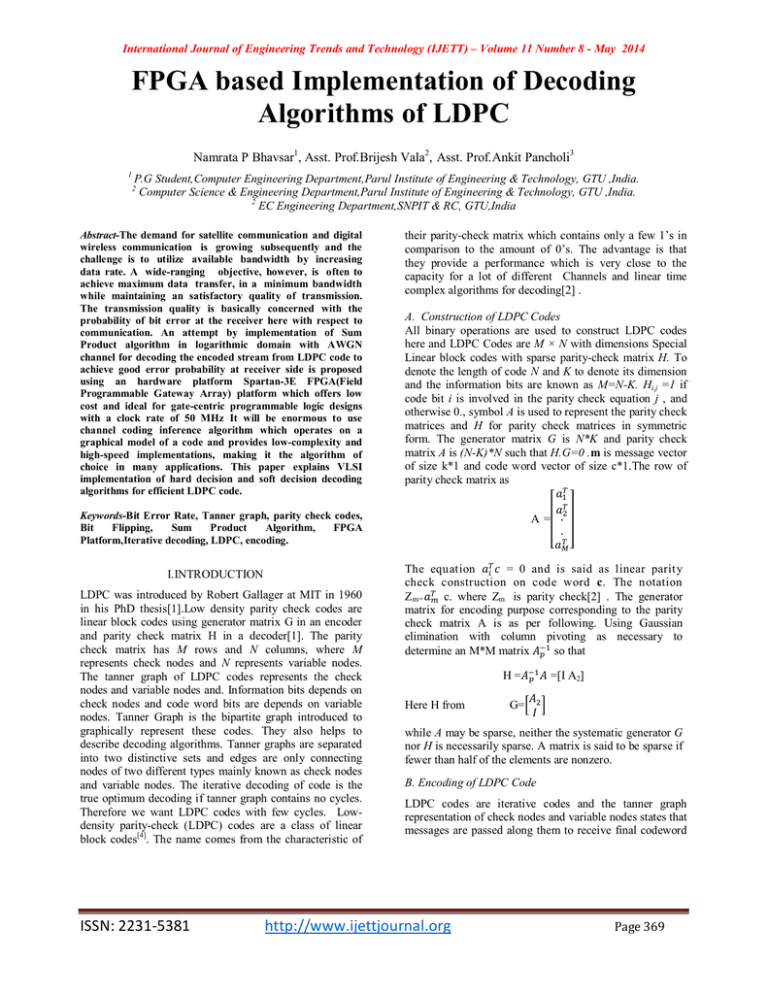
International Journal of Engineering Trends and Technology (IJETT) – Volume 11 Number 8 - May 2014 FPGA based Implementation of Decoding Algorithms of LDPC Namrata P Bhavsar1, Asst. Prof.Brijesh Vala2, Asst. Prof.Ankit Pancholi3 1 P.G Student,Computer Engineering Department,Parul Institute of Engineering & Technology, GTU ,India. Computer Science & Engineering Department,Parul Institute of Engineering & Technology, GTU ,India. 2 EC Engineering Department,SNPIT & RC, GTU,India 2 Abstract-The demand for satellite communication and digital wireless communication is growing subsequently and the challenge is to utilize available bandwidth by increasing data rate. A wide-ranging objective, however, is often to achieve maximum data transfer, in a minimum bandwidth while maintaining an satisfactory quality of transmission. The transmission quality is basically concerned with the probability of bit error at the receiver here with respect to communication. An attempt by implementation of Sum Product algorithm in logarithmic domain with AWGN channel for decoding the encoded stream from LDPC code to achieve good error probability at receiver side is proposed using an hardware platform Spartan-3E FPGA(Field Programmable Gateway Array) platform which offers low cost and ideal for gate-centric programmable logic designs with a clock rate of 50 MHz It will be enormous to use channel coding inference algorithm which operates on a graphical model of a code and provides low-complexity and high-speed implementations, making it the algorithm of choice in many applications. This paper explains VLSI implementation of hard decision and soft decision decoding algorithms for efficient LDPC code. their parity-check matrix which contains only a few 1’s in comparison to the amount of 0’s. The advantage is that they provide a performance which is very close to the capacity for a lot of different Channels and linear time complex algorithms for decoding[2] . A. Construction of LDPC Codes All binary operations are used to construct LDPC codes here and LDPC Codes are M × N with dimensions Special Linear block codes with sparse parity-check matrix H. To denote the length of code N and K to denote its dimension and the information bits are known as M=N-K. Hi,j =1 if code bit i is involved in the parity check equation j , and otherwise 0., symbol A is used to represent the parity check matrices and H for parity check matrices in symmetric form. The generator matrix G is N*K and parity check matrix A is (N-K)*N such that H.G=0 .m is message vector of size k*1 and code word vector of size c*1.The row of parity check matrix as ⎡ ⎤ ⎢ ⎥ A =⎢ . ⎥ ⎢ . ⎥ ⎣ ⎦ Keywords-Bit Error Rate, Tanner graph, parity check codes, Bit Flipping, Sum Product Algorithm, FPGA Platform,Iterative decoding, LDPC, encoding. I.INTRODUCTION LDPC was introduced by Robert Gallager at MIT in 1960 in his PhD thesis[1].Low density parity check codes are linear block codes using generator matrix G in an encoder and parity check matrix H in a decoder[1]. The parity check matrix has M rows and N columns, where M represents check nodes and N represents variable nodes. The tanner graph of LDPC codes represents the check nodes and variable nodes and. Information bits depends on check nodes and code word bits are depends on variable nodes. Tanner Graph is the bipartite graph introduced to graphically represent these codes. They also helps to describe decoding algorithms. Tanner graphs are separated into two distinctive sets and edges are only connecting nodes of two different types mainly known as check nodes and variable nodes. The iterative decoding of code is the true optimum decoding if tanner graph contains no cycles. Therefore we want LDPC codes with few cycles. Lowdensity parity-check (LDPC) codes are a class of linear block codes[4]. The name comes from the characteristic of ISSN: 2231-5381 The equation = 0 and is said as linear parit y check construction on code word c. The notation Z m= c. where Zm is parity check[2] . The generator matrix for encoding purpose corresponding to the parity check matrix A is as per following. Using Gaussian elimination with column pivoting as necessary to determine an M*M matrix so that H= Here H from =[I A2] G= while A may be sparse, neither the systematic generator G nor H is necessarily sparse. A matrix is said to be sparse if fewer than half of the elements are nonzero. B. Encoding of LDPC Code LDPC codes are iterative codes and the tanner graph representation of check nodes and variable nodes states that messages are passed along them to receive final codeword http://www.ijettjournal.org Page 369 International Journal of Engineering Trends and Technology (IJETT) – Volume 11 Number 8 - May 2014 to match it with received word. Encoding of codes, having higher block lengths can be quite difficult to implement in hardware but there are several methods of generating H such that encoding can be done via shift registers. If the generator matrix G of a linear block code is known then encoding can be done using Parity check matrix[2].The cost of the method depends on the Hamming weights i.e. the no of 1’s of the basis vectors of G., The cost of encoding using this method is proportional to n2[9],if the vector are dense. If G is sparse then this cost becomes linear with n. It is unlikely that the generator matrix G will also be sparse. So one of the straightforward method of encoding LDPC that would require number of operations which is proportional to n2. As this is too slow for most practical applications, It is desirable to have encoding that run in linear time. Here noted earlier that a generator matrix G for a code with parity-check matrix H can be found by performing Gauss-Jordan elimination on H to obtain it in the form H=[ concurrent area- and speed-optimized hardware operations. Then after introducing the concept of time by adding clocks and clock rates to schedule the operations in hardware and creating resource-shared architectures to implement expensive operators like multipliers and forloop bodies. The following kit diagram represented here. ] Where A is (n-k)×k binary matrix and is the size n-k identity matrix. The generator matrix is then G=[ ] Now at here we can encode this message into code words for LDPC Codes which requires the generation of parity check matrix H[2] . The encoding method is through the use of a generator matrix, denoted by G. A code word c is formed by multiplying source message u by the matrix which is represented as c=u*G. The parity check equations of the LDPC code contains constraints which are recognized from matrix G.For a binary code if it is given that having k message bits and length of the codeword is n, then the generator matrix G is a (k *n) binary matrix having the form = . Here GHT = 0 as the row space of G will be orthogonal to H. The process of converting H into the generator matrix G has the effect of causing G to lose the sparseness characteristic that was embodied in H. C.Orientation of paper Section I contains introduction for LDPC code encoding of LDPC codes. Decoding of LDPC codes is in Section II. Section III contains overview of FPGA spartan 3E platform. Section IV contains Results and analysis. Finally in Section V indicates conclusion is i.e to increase data rate. II.OVERVIEW OF FPGA SPARTAN 3E PLATFORM Implementing MATLAB code here involves feature of the above kit like Converting floating-point MATLAB code to fixed-point MATLAB code with optimized bit widths which is suitable for efficient hardware generation. Identifying and mapping procedural constructs to ISSN: 2231-5381 Fig 1 : FPGA SPARTAN 3E kit[8] Feature of kit involves Very low cost, high-performance logic solution for high-volume consumer-oriented applications Multi-voltage, multi-standard Select IO interface pins ,Up to 376 I/O pins or 156 differential signal pairs ,LVCMOS, LVTTL, HSTL, and SSTL single-ended signal standards& 622+ Mb/s data transfer rate per I/O, Enhanced Double Data Rate (DDR) support ,DDR SDRAM support up to 333 Mb/s, flexible logic resources, Efficient wide multiplexers, wide logic ,Fast look-ahead carry logic ,Enhanced 18 x 18 multipliers with optional pipeline ,Frequency synthesis, multiplication, division[8]. III. Decoding of LDPC Code There are different iterative decoding algorithms having two derivations. They are mainly classified as in hard decision decoding and soft decision decoding respectively. Bit flipping is hard decision decoding algorithm and Sum Product is soft decision decoding algorithm. A. Hard Decision Decoding In this hard decoding scheme the check nodes finds the bit in error by checking the parity which may be even or odd and the messages from variable nodes are transmitted to check nodes, check node checks the parity of the data stream received *from variable nodes connected to it. If number of 1‘s received at check nodes satisfies the required parity, then it sends the same data back to message node, else it adjusts each bit in the received data stream to satisfy the required parity and then transmits the new message back to message nodes. So to fulfil the parity check equation, here in case each node fj looks at the message http://www.ijettjournal.org Page 370 International Journal of Engineering Trends and Technology (IJETT) – Volume 11 Number 8 - May 2014 received from the variable nodes and calculates the bit that the fourth variable node should have n order. B. Soft Decision Decoding Soft-decision decoding is based on the concept of belief propagation that yield in a enhanced decoding performance where LDPC codes gives best performance. The messages are the conditional probability that in the given received vector received bit is a 1 or a 0 in soft scheme here . The sum-product algorithm is a soft decision message-passing algorithm. The input bit probabilities were known in advance before running the LDPC decoder and they are called the a priori probabilities for the received bits. posterior probabilities are the bit probabilities returned by the decoder. Mj, i’ = LLR( ,′ ,′ ) = log( ) ,′ Here Each bit has access to the input a priori LLR, ri, and the LLRs from every connected check node. The total LLR of the i-th bit is the sum of these LLRs: = LLR( ) = ri + ∑ . ……….. (4) ∈ Here the results of hard and soft decision decoding algorithms are compared in the following figure 1 which shows better BER performance for soft decision decoding algorithms IV. RESULT ANALYSIS The sum-product algorithm is a soft decision messagepassing algorithm which is similar to the bit-flipping algorithm but it is implemented in logarithmic domain to get better BER rate with the SNR ratios. To understand logarithmic domain Likelihood ratios are introduced here to do so. They are used to represent the metrics for a binary variable by a single value as per following: ( ) L(x) = Log( ( )) Fig 2 : BER performance of hard & soft decision decoding algorithms The aim of sum-product decoding algorithm here is first to compute the maximum a posteriori probability (MAP) for each codeword bit. Now here it is the probability that the ith codeword bit is a 1 conditional on the event N and that all parity-check constraints are satisfied. The sum-product algorithm iteratively computes an approximation of the MAP value for each code bit.The a posteriori probabilities returned by the sum-product decoder are only exact MAP probabilities if the Tanner graph is cycle free[3] .The extra information about bit i received from the parity-checks is called as extrinsic information for bit i. The probability that the parity-check equation is satisfied if bit i is a 1 is, The results on the hardware kit FPGA Sparten 3e are shown here with the following tables. Table I : Device utilization summery of a (M=8, N=16) SPA decoder Sr. No 1 2 3 = - , ′∈ (1-2 , ′ ) ………….(1) ′ Where . is the current estimate, available to check j, of the probability that bit i‘ is a one. If bit i is a zero, The probability that the parity-check equation is satisfied is thus (1 - , ). Here it is expressed as a log-likelihood ratio, . = LLR( , , ) = log( )………….(2) ∈ ,′ ( ∈ ,′ ( Where ISSN: 2231-5381 5 Used Available 938 4,896 Utilized in SPA 19% 1,799 4,896 36% 1,169 1,169 100% 142 172 82% 5 12 41% , And substituting (2) we get Ei,j = log( 4 Slice Logic block Number of Slice Flip Flops Number of 4-input LUTs Number of Occupied Slices for logic Nu of IO blocks Number of RAM blocks ,′ ,′ ) ) )……..(3) The implementation of decoder in SPA is lot more complex then encoder because it requires more computational units, use of large array of data and more storage requirements. This decoder utilizes the total 1.169 slices out of 2.448 slices means 47% utilization of slices. Other utilization http://www.ijettjournal.org Page 371 International Journal of Engineering Trends and Technology (IJETT) – Volume 11 Number 8 - May 2014 summery is given in above table. The Synthesis report of the decoder produces RTL models as a output. These RTL schematics describe the operations in terms of flow of signals in Hardwires. Table II : BER Analysis of Log Domain Sum product algorithm on Spartan3E SR No. 1 2 3 4 Applied SNRs in dB 0 to 2 2 to 4 4 to 6 6 to 8 Achieved BER No’s of Iterations 10-1 10-2 10-3 -4 10 to 10-5 I = Max 50 I = Max 50 I = Max 50 I = Max 50 The table above 5.2 contains different SNR range and in that range BER on the SPARTEN 3E board with maximum number of iterations =50. V. CONCLUSION AND FUTURE WORK Communication standards to achieve higher data rate has become a primary concern across several fields in today’s world. There are various coding Techniques with different parameter Concern tried to get this. One of the most famous name which can approach channel capacity.To improve the efficiency of communication system is the purpose of coding theory. From the simulation results carried out on a MATLAB-2012 with the required Eb/No range from 0 to 15 dB it is observed that LDPC codes are more suitable to applications which need reliable transmission of information with a bit error rate of 10-5 compared to convolution code. By comparing the performance parameters for both of the decoding algorithm its clear that SPA provides good BER. The work can be extended for high block length H matrix and for BER up to 10 . The decoder can be redesigned for higher code rate. An irregular LDPC code can be used with these decoders in order to improve the error performance. This FPGA designs would improve the error performance of the decoder and will be implemented and compared with literature data. VII. REFERENCES [1] R. G. Gallager, ‘Low-Density Parity-Check Codes’. Cambridge, MA: M.I.T. Press, 1963. [2] Analysis and implementation of soft decision decoding algorithm of ldpc, m. M. Jadhav, ankit pancholi, dr. A. M. Sapkal asst. Professor, e&tc, scoe, pune university phase-i, d,-402, g.v 7, ambegaon, pune (india),[IJETT],2013. [3] Iterative Decoding schemes of LDPC codes, Ashish Patil, Sushil Sonavane, Prof. D. P. Rathod / International Journal of Engineering Research and Applications (IJERA), March -April 2013. [4]LDPC Codes – a brief Tutorial,Bernhard M.J. Leiner, Stud.ID.: 53418L bleiner@gmail.com,April 8, 2005. [5]Introducing Low-Density Parity-Check, Codes,Sarah J. Johnson, School of Electrical Engineering and Computer Science, The University of Newcastle, Australia. [6]Systematic construction, verification and implementation methodology for LDPC codes Hui Yu*, Jing Cui, Yixiang Wang and Yibin Yang,Springer. [7] An introduction to LDPC codes, William E Ryan, department of electrical and computer engineering. The University of Arizona,Australia,2003. [8] Spartan-3E Starter Kit Board User Guide ,UG230 (v1.0) March 9, 2006 [9] Modern Digital and analog communication system and solution., B.P Lathi, Oxferd University Press. VI. ACKNOWLEDGEMENTS A whole heartedly thank Mr. Brijesh Vala for all his diligence, guidance, encouragement, inspiration and motivation and my mother and father for the support throughout and to thank anonymous reviewers for their valuable suggestions. ISSN: 2231-5381 http://www.ijettjournal.org Page 372
