Hydrogen Hybrid Locomotive
advertisement
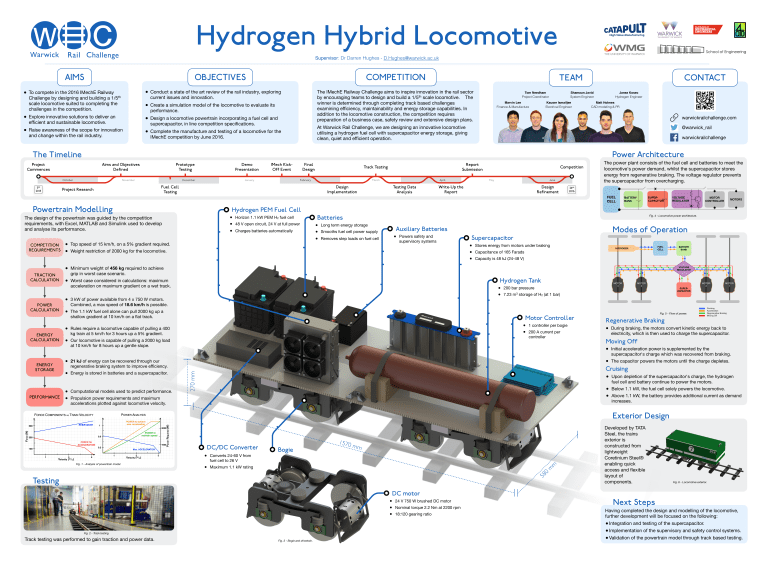
Hydrogen Hybrid Locomotive Supervisor: Dr Darren Hughes - D.Hughes@warwick.ac.uk AIMS • OBJECTIVES To compete in the 2016 IMechE Railway Challenge by designing and building a 1/5th scale locomotive suited to completing the challenges in the competition. • awareness of the scope for innovation • Raise and change within the rail industry. Explore innovative solutions to deliver an efficient and sustainable locomotive. COMPETITION a state of the art review of the rail industry, exploring • Conduct current issues and innovation. a simulation model of the locomotive to evaluate its • Create performance. a locomotive powertrain incorporating a fuel cell and • Design supercapacitor, in line competition specifications. Complete the manufacture and testing of a locomotive for the • IMechE competition by June 2016. TEAM The IMechE Railway Challenge aims to inspire innovation in the rail sector by encouraging teams to design and build a 1/5th scale locomotive. The winner is determined through completing track based challenges examining efficiency, maintainability and energy storage capabilities. In addition to the locomotive construction, the competition requires preparation of a business case, safety review and extensive design plans. Tom Needham Project Coordinator Marvin Lee Finance & Manufacture Shamaun Javid System Engineer Kauser Ismailjee Electrical Engineer Janez Kosec Hydrogen Engineer Matt Holmes CAD modeling & PR warwickrailchallenge.com At Warwick Rail Challenge, we are designing an innovative locomotive utilising a hydrogen fuel cell with supercapacitor energy storage, giving clean, quiet and efficient operation. @warwick_rail warwickrailchallenge Power Architecture The Timeline Project Commences Aims and Objectives Defined October 5th 2015 CONTACT Prototype Testing November Project Research Demo Presentation December IMech KickOff Event January Final Design Report Submission Track Testing February March Fuel Cell Testing April Design Implementation Testing Data Analysis Competition May June Write-Up the Report Design Refinement The power plant consists of the fuel cell and batteries to meet the locomotive's power demand, whilst the supercapacitor stores energy from regenerative braking. The voltage regulator prevents the supercapacitor from overcharging. 24th 2016 FUEL CELL Powertrain Modelling POWER CALCULATION ENERGY CALCULATION • • • ENERGY STORAGE PERFORMANCE Horizon 1.1 kW PEM H2 fuel cell 48 V open circuit, 24 V at full power Charges batteries automatically • Top speed of 15 km/h, on a 5% gradient required. • Weight restriction of 2000 kg for the locomotive. Batteries • • • Long term energy storage • Removes step loads on fuel cell Powers safety and supervisory systems MOTORS Supercapacitor • • • Stores energy from motors under braking Capacitance of 165 Farads Capacity is 48 kJ (24-48 V) Hydrogen Tank • • kW of power available from 4 x 750 W motors. • 3Combined, a max speed of 18.6 km/h is possible. 1.1 kW fuel cell alone can pull 2000 kg up a • The shallow gradient at 10 km/h on a flat track. 200 bar pressure 7.23 m3 storage of H2 (at 1 bar) Motor Controller • • • locomotive is capable of pulling a 2000 kg load • Our at 10 km/h for 8 hours up a gentle slope. Rules require a locomotive capable of pulling a 400 kg train at 5 km/h for 3 hours up a 5% gradient. • Computational models used to predict performance. power requirements and maximum • Propulsion accelerations plotted against locomotive velocity. MOTOR CONTROLLER Modes of Operation Auxiliary Batteries Smooths fuel cell power supply weight of 456 kg required to achieve • Minimum grip in worst case scenario. case considered in calculations: maximum • Worst acceleration on maximum gradient on a wet track. kJ of energy can be recovered through our • 21 regenerative braking system to improve efficiency. • Energy is stored in batteries and a supercapacitor. VOLTAGE REGULATOR Fig. 4 - Locomotive power architecture. 1 controller per bogie 200 A current per controller Fig. 5 - Flow of power. Regenerative Braking braking, the motors convert kinetic energy back to • During electricity, which is then used to charge the supercapacitor. Moving Off acceleration power is supplemented by the • Initial supercapacitor's charge which was recovered from braking. • The capacitor powers the motors until the charge depletes. Cruising depletion of the supercapacitor's charge, the hydrogen • Upon fuel cell and battery continue to power the motors. • Below 1.1 kW, the fuel cell solely powers the locomotive. 1.1 kW, the battery provides additional current as demand • Above increases. 270 mm TRACTION CALCULATION SUPERCAPACITOR Hydrogen PEM Fuel Cell The design of the powertrain was guided by the competition requirements, with Excel, MATLAB and Simulink used to develop and analyse its performance. COMPETITION REQUIREMENTS BATTERY BANK Exterior Design DC/DC Converter Fig. 1 - Analysis of powertrain model. • • Converts 24-60 V from fuel cell to 26 V Bogie 1570 mm Maximum 1.1 kW rating 0 8 5 Testing m m Developed by TATA Steel, the trains exterior is constructed from lightweight Coretinium Steel® enabling quick access and flexible layout of components. Fig. 6 - Locomotive exterior. DC motor • • • 24 V 750 W brushed DC motor Nominal torque 2.2 Nm at 2200 rpm 18:120 gearing ratio Next Steps Having completed the design and modelling of the locomotive, further development will be focused on the following: • • Implementation of the supervisory and safety control systems. • Validation of the powertrain model through track based testing. Integration and testing of the supercapacitor. Fig. 2 - Track testing. Track testing was performed to gain traction and power data. Fig. 3 - Bogie and drivetrain.
