Data Communication at receiver end of AVIONICS System 5
advertisement

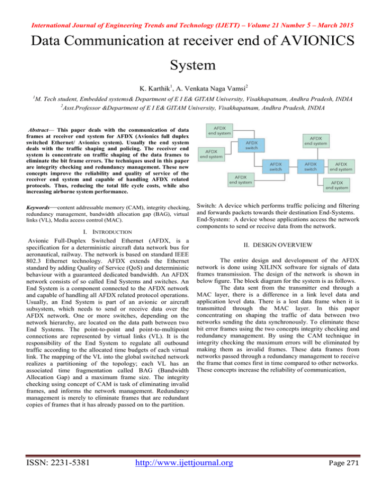
International Journal of Engineering Trends and Technology (IJETT) – Volume 21 Number 5 – March 2015 Data Communication at receiver end of AVIONICS System K. Karthik1, A. Venkata Naga Vamsi2 1 M. Tech student, Embedded systems& Department of E I E& GITAM University, Visakhapatnam, Andhra Pradesh, INDIA 2 Asst.Professor &Department of E I E& GITAM University, Visakhapatnam, Andhra Pradesh, INDIA Abstract— This paper deals with the communication of data frames at receiver end system for AFDX (Avionics full duplex switched Ethernet/ Avionics system). Usually the end system deals with the traffic shaping and policing. The receiver end system is concentrate on traffic shaping of the data frames to eliminate the bit frame errors. The techniques used in this paper are integrity checking and redundancy management. These new concepts improve the reliability and quality of service of the receiver end system and capable of handling AFDX related protocols. Thus, reducing the total life cycle costs, while also increasing airborne system performance. Keywords—content addressable memory (CAM), integrity checking, redundancy management, bandwidth allocation gap (BAG), virtual links (VL), Media access control (MAC). I. INTRODUCTION Avionic Full-Duplex Switched Ethernet (AFDX, is a specification for a deterministic aircraft data network bus for aeronautical, railway. The network is based on standard IEEE 802.3 Ethernet technology. AFDX extends the Ethernet standard by adding Quality of Service (QoS) and deterministic behaviour with a guaranteed dedicated bandwidth. An AFDX network consists of so called End Systems and switches. An End System is a component connected to the AFDX network and capable of handling all AFDX related protocol operations. Usually, an End System is part of an avionic or aircraft subsystem, which needs to send or receive data over the AFDX network. One or more switches, depending on the network hierarchy, are located on the data path between two End Systems. The point-to-point and point-to-multipoint connections are represented by virtual links (VL). It is the responsibility of the End System to regulate all outbound traffic according to the allocated time budgets of each virtual link. The mapping of the VL into the global switched network realizes a partitioning of the topology; each VL has an associated time fragmentation called BAG (Bandwidth Allocation Gap) and a maximum frame size. The integrity checking using concept of CAM is task of eliminating invalid frames, and informs the network management. Redundancy management is merely to eliminate frames that are redundant copies of frames that it has already passed on to the partition. ISSN: 2231-5381 Switch: A device which performs traffic policing and filtering and forwards packets towards their destination End-Systems. End-System: A device whose applications access the network components to send or receive data from the network. II. DESIGN OVERVIEW The entire design and development of the AFDX network is done using XILINX software for signals of data frames transmission. The design of the network is shown in below figure. The block diagram for the system is as follows. The data sent from the transmitter end through a MAC layer, there is a difference in a link level data and application level data. There is a lost data frame when it is transmitted through the MAC layer. In this paper concentrating on shaping the traffic of data between two networks sending the data synchronously. To eliminate these bit error frames using the two concepts integrity checking and redundancy management. By using the CAM technique in integrity checking the maximum errors will be eliminated by making them as invalid frames. These data frames from networks passed through a redundancy management to receive the frame that comes first in time compared to other networks. These concepts increase the reliability of communication, http://www.ijettjournal.org Page 271 International Journal of Engineering Trends and Technology (IJETT) – Volume 21 Number 5 – March 2015 The ES should provide logical isolation with respect to available bandwidth among the Virtual Link(s) it supports. Regardless of the attempted utilization of a VL by one partition, the available Bandwidth on any other VL is unaffected. For each Virtual Link, the End System should maintain the ordering of data as delivered by a partition, for both transmission and reception (ordinal integrity). To guarantee the BAG for each VL the frame flow is regulated as due to the bit error the frames will be lost in application level at receiver end. A. Bandwidth allocation gap (BAG): The data frame delivery follows a bounded arrival distribution. This bounded arrival implies exact bandwidth regulated traffic flow control. Therefore, the distribution of latency on each connection through the network follows a distribution, which is bounded. This results in a calculable maximum latency in the network, rather than a probabilistic latency. Using exact bandwidth regulated traffic control it is possible to limit the bandwidth usage over any arbitrarily small interval of time. Therefore, it is possible to limit a bandwidth fault effect of an end system. The figure for maximum bandwidth flow is shown below figure C. media access control (MAC): The MAC uses the Ethernet fame format for the communication between the transmitter end devices to the receiver end devices. To avoid losing incoming frames during a burst, and to fix the IFG in transmission, the MAC layer of the end-system should be able to: Process received frames at full frame rate of the medium and appropriate (selected) frames are made available to the partition at full frame rate of the medium Transmit frames back to back The BAG size should always be greater than frame size. So, the frame errors in transmission are reduced. AFDX frame structure is B. Virtual link (VL): An end system may be designed to only receive VLs and not transmit VLs, or the contrary; therefore, an ES can originate or receive zero VLs. End-systems exchange Ethernet frames through VL. Only one End System within the Avionics network should be the source of any one VL. A Virtual Link defines a logical unidirectional connection from one source end-system to one or more destination end-systems. The transmission of data frames at transmitter end is Each Virtual Link has a dedicated maximum bandwidth. This bandwidth is allocated by the System Integrator. ISSN: 2231-5381 Frame size: 64-1518bits The source address is unicast address. The destination address is multicast address. Frame check sequence enables receiving interface to detect errors in received frame. The Destination Address identifies the Virtual Link D. Content addressable memory: Content-addressable memory (CAM) is a special type of computer memory used in certain very-high-speed searching applications. It compares input search data against a table of stored data, and returns the address of matching data http://www.ijettjournal.org Page 272 International Journal of Engineering Trends and Technology (IJETT) – Volume 21 Number 5 – March 2015 CAM is often used in computer network devices, so the destination port can be found very quickly, reducing the switch's latency. CAM consists of a table of contents which consists of data and memory, CAM is useful for matching the data‘s and checking the valid data. E. Integrity checking: Integrity checking is done per VL and per Network Checking is based on Sequence Number (SN) and so called ―Maximum Consecutive Frames Lost‖ The Sequence numbering is performed for each VL individually Integrity Checking has the task of eliminating invalid frames, and informs the network management. Under fault-free network operation, the Integrity Checking simply passes the frames that it has received on to the Redundancy Management, independently for each network. If there are faults (based on sequence number), the Integrity Checking has the task of eliminating invalid frames, and informs the network management accordingly. For each network the Integrity Checking tests each frame for a sequence number in the interval: [PSN‖+‖1, PSN‖+‖2] Previous Sequence Number (PSN) is the sequence number of the previous frame received (but not necessarily forwarded) on this VL. The operator ―+‖ takes the wrap-around of Sequence Numbers into account. So, for example if PSN = 254 then PSN‖+‖1= 255 and PSN‖+‖2 = 1. The Integrity Checking should also accept the frame as valid in the following special cases: The Received Sequence Number (RSN) is equal to 0 The frame is the first frame received after any reset of the receiving ES Frames that do not meet these criteria are discarded. F. Integrity checking using CAM: ISSN: 2231-5381 CAM consists of a data table which is passed at the transmitter end. The data from the MAC layer is passed through a CAM. If the data matches with the CAM table then it sends the output data with the addition of the sequence number ‗1‘ and the corresponding address is generated from the memory. If the data doesn‘t matches with the CAM memory then it sends the output data as ‗0‘ and the corresponding address ‗0‘ is generated from the memory. These generated outputs are passed into the redundancy management where the first arrival wins first. The waveforms of integrity checking are shown in below waveforms. G. Redundancy management: The function of the AFDX redundancy management is merely to eliminate frames that are redundant copies of frames that it has already passed on to the partition. The Redundancy Management (RM) assumes that the network is working properly and, in particular, the deterministic properties are verified. Definitions: Redundant VL means that the same frames are sent through both network, A and B Non-redundant VL means that (possibly different) frames are sent through either network A or B On a per VL basis, the ES should be able to receive: A redundant VL and deliver to the partition one of the redundant data (RM active) A redundant VL and deliver to the partition both redundant data (RM not active) A non redundant VL on either interface and submit data from it to the partition (in this case, RM can be active or not) This RM function should be configurable. When redundancy management is active, it should deliver the first of the redundant frames received. Reset of any equipment involved in the communication (transmitting End system, receiving End system or the AFDX switch) should not affect this property. This ―First Win‖ philosophy enables availability of the network in the case of one AFDX switch loss. The waveforms of redundancy management algorithm is http://www.ijettjournal.org Page 273 International Journal of Engineering Trends and Technology (IJETT) – Volume 21 Number 5 – March 2015 The program for this system is written by using the VHDL and VERILOG in XILINX software. III. CONCLUSION AND FUTURE SCOPE In above waveforms the transmitted data frames are lost at receiving frames while passing from MAC layer. These received waveforms are passed through integrity checking using CAM. Here, the valid data is transmitted and invalid data is eliminated. The data frames two networks are checked and first arrival wins first the data at receiver end system. In redundancy management the first arrival wins of the two networks. The output waveforms of redundancy management is shown in below waveforms H. Waveforms: The waveforms for integrity checking using CAM is The Avionics network traffic shaping is simple by using the integrity checking with concept of CAM and redundancy management. The reliability of the system increases, reducing the total life costs and air borne system performance increases. This technique is used for the communication in aircrafts and railways; even in tough terrain conditions the data communication takes place without loss of information. This concept can be implemented in FPGA to improve the reliability of system performance practically. As the speed of Ethernet is high the speed of communication is high. Hence, in real time systems this technique improves speed and accuracy of the system by eliminating the errors. References [1] ―Actel Developing Solutions, Developing AFDX solutions‖. [2] ―A probabilistic Analysis of END–TO–END Delays on an AFDX Avionics Network‖, Jean-Luc Scharbarg, Frederic Ridouard, Christian Fraboul. [3] ―AFDX/ARINC 664 Protocol Tutorial‖, GE FANUC Embedded Systems. [4] Ian Land, Jeff Elliott, ―Architecting ARINC 664‖, Part 7 (AFDX) Solutions. [5] ―ARINC Tutorial‖, Condor Engineering. [6] ―AFDX /ARINC 664 Protocol Tutorials‖, TECHSAT Germany. [7] [Online] Available: http://www.arinc.com [8] AFDX/ARINC 664 Protocol, Tutorial – GE Fanuc [9] AIRCRAFT DATA NETWORK PART 7 AFDX The waveforms for redundancy management is E. SOFTWARE DESIGN ISSN: 2231-5381 http://www.ijettjournal.org Page 274


