Audio Signal Compression using DCT and LPC Techniques
advertisement

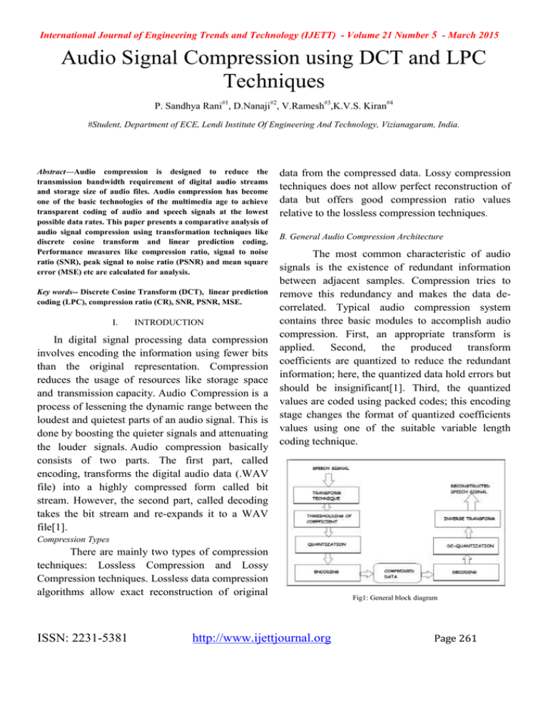
International Journal of Engineering Trends and Technology (IJETT) - Volume 21 Number 5 - March 2015 Audio Signal Compression using DCT and LPC Techniques P. Sandhya Rani#1, D.Nanaji#2, V.Ramesh#3,K.V.S. Kiran#4 #Student, Department of ECE, Lendi Institute Of Engineering And Technology, Vizianagaram, India. sandhyapatnayakuni@gmail.com Abstract—Audio compression is designed to reduce the transmission bandwidth requirement of digital audio streams and storage size of audio files. Audio compression has become one of the basic technologies of the multimedia age to achieve transparent coding of audio and speech signals at the lowest possible data rates. This paper presents a comparative analysis of audio signal compression using transformation techniques like discrete cosine transform and linear prediction coding. Performance measures like compression ratio, signal to noise ratio (SNR), peak signal to noise ratio (PSNR) and mean square error (MSE) etc are calculated for analysis. Key words-- Discrete Cosine Transform (DCT), linear prediction coding (LPC), compression ratio (CR), SNR, PSNR, MSE. I. INTRODUCTION In digital signal processing data compression involves encoding the information using fewer bits than the original representation. Compression reduces the usage of resources like storage space and transmission capacity. Audio Compression is a process of lessening the dynamic range between the loudest and quietest parts of an audio signal. This is done by boosting the quieter signals and attenuating the louder signals. Audio compression basically consists of two parts. The first part, called encoding, transforms the digital audio data (.WAV file) into a highly compressed form called bit stream. However, the second part, called decoding takes the bit stream and re-expands it to a WAV file[1]. data from the compressed data. Lossy compression techniques does not allow perfect reconstruction of data but offers good compression ratio values relative to the lossless compression techniques. B. General Audio Compression Architecture The most common characteristic of audio signals is the existence of redundant information between adjacent samples. Compression tries to remove this redundancy and makes the data decorrelated. Typical audio compression system contains three basic modules to accomplish audio compression. First, an appropriate transform is applied. Second, the produced transform coefficients are quantized to reduce the redundant information; here, the quantized data hold errors but should be insignificant[1]. Third, the quantized values are coded using packed codes; this encoding stage changes the format of quantized coefficients values using one of the suitable variable length coding technique. Compression Types There are mainly two types of compression techniques: Lossless Compression and Lossy Compression techniques. Lossless data compression algorithms allow exact reconstruction of original ISSN: 2231-5381 http://www.ijettjournal.org Fig1: General block diagram Page 261 International Journal of Engineering Trends and Technology (IJETT) - Volume 21 Number 5 - March 2015 II. expresses a sequence of finite data points in terms of sum of cosine functions. DCT Discrete Cosine Transform can be used for audio compression because of high correlation in adjacent coefficients. We can reconstruct a sequence very accurately from very few DCT coefficients. This property of DCT helps in effective reduction of data. Where m=0, 1, - - - - - -, N-1. The inverse discrete cosine transform is DCT technique removes certain frequencies from audio data such that the size is reduced with reasonable quality. It is a first level of approximation to mpeg audio compression, which are more sophisticated forms of the basic principle used in DCT. This DCT compression is performed in MATLAB and it takes the wave file as input, compress it to different levels and assess the output that is each compressed wave file[3]. The difference in their frequency spectra will be viewed to assess how different levels of compression affect the audio signals. III. In both equations Cm can be defined as Cm= (1/2)1/2 for m=0 and Cm=1 for m≠0. DCT is widely used transform in image and video compression algorithms. Its popularity is mainly due to the fact that it achieves a good data compaction; because it concentrates the information content in a relatively few transform coefficients. Its basic operation is to take the input audio data and transforms it from one type of representation to another, in our case the signal is a block of audio samples. The concept of this transformation is to transform a set of points from the spatial domain into an identical representation in frequency domain[3]. It identifies pieces of information that can be effectively thrown away without seriously reducing the audio's quality. This transform is very common when encoding video and audio tracks on computers. Many "codecs" for movies rely on DCT concepts for compressing and encoding video files. The DCT can also be used to analyze the spectral components of images as well. The DCT is very similar to the DFT, except the output values are all real numbers, and the output vector is approximately twice as long as the DFT output. It ISSN: 2231-5381 LPC Linear predictive coding is a tool mostly used in audio signal processing and speech processing for representing the spectral envelope of digital signal of speech in compressed form, using the information of linear predictive model. It is one of the most powerful speech analysis techniques, and one of the most useful techniques for encoding good quality signal at low bitrates and provides extremely accurate estimates of parameters. LPC analyzes the signal by estimating the formants, removing their effects from the speech signal, and estimating the intensity and frequency of the remaining buzz. The process of removing the formants is called inverse filtering, and the remaining signal after the subtraction of the filtered modeled signal is called the residue[2]. LPC is generally used for speech analysis and re synthesis. It is used as a form of voice compression by phone companies, for example in the GSM standard. It is also used for secure wireless where voice should be digitized, encrypted and sent over a narrow voice channel. http://www.ijettjournal.org Page 262 International Journal of Engineering Trends and Technology (IJETT) - Volume 21 Number 5 - March 2015 A .Advantages and Limitations of LPC: Its main advantage comes from the reference to a simplified vocal tract model and the analogy of a source-filter model with the speech production system. It is a useful methods for encoding speech at a low bit rate. LPC performance is limited by the method itself, and the local characteristics of the signal. The harmonic spectrum sub-samples the spectral envelope, which produces a spectral aliasing. These problems are especially manifested in voiced and high-pitched signals, affecting the first harmonics of the signal, which refer to the perceived speech quality and formant dynamics. A correct all-pole model for the signal spectrum can hardly be obtained. The desired spectral information, the spectral envelope is not represented : we get too close to the original spectra. The LPC follows the curve of the spectrum down to the residual noise level in the gap between two harmonics, or partials spaced too far apart[2]. It does not represent the desired spectral information to be modeled since we are interested in fitting the spectral envelope as close as possible and not the original spectra. The spectral envelope should be a smooth function passing through the prominent peaks of the spectrum, yielding a flat sequence, and not the "valleys" formed by the harmonic peaks. IV. DCT AUDIO COMPRESSION ARCHITECTURE Figure 2: Block diagram of DCT A.Process: Read the audio file using waveread ( ) built in function. Determine a value for the number of samples that will undergo a DCT at once. In other words, the audio vector will be divided into pieces of this length. Again, we examine at different compression rates say 50%, 75%, 87.5%. Initialize compressed matrices and set different compression percentage Perform actual compression and use any loop we have used for loop for getting all the signals. Inside the loop take dct () of the input and compressed signal i.e convert the signal in form of frequencies. Then get the signal back by applying the idct () and plot the audio signals also plot the portion of audio signals as expanded view and plot the spectrogram of audio signal save to wave file and play the files. V. LPC AUDIO COMPRESSION ARCHITECTURE LPC is generally used for speech analysis and re-synthesis. It is used as a form of voice compression by phone companies. The Discrete Cosine Transform (DCT) is very commonly used when encoding video and audio tracks on computers. ISSN: 2231-5381 http://www.ijettjournal.org Page 263 International Journal of Engineering Trends and Technology (IJETT) - Volume 21 Number 5 - March 2015 Where N is the length of reconstructed signal, X is the maximum absolute square value of signal x and ||x-x`||2 is the energy of the difference between the original and reconstructed signal. C.Mean Square Error (MSR): Figure 2: Block diagram of LPC A.Process: Read the audio file and digitize the analog signal. For each segment determine the key features. Encode the features as accurately as possible. The data is passed over the network in which noise may be added. The obtained signal is decoded at the receiver. VI. PERFORMANCE EVALUATION To evaluate the overall performance of proposed audio Compression scheme, several objective tests were made. To measure the performance of the reconstructed signal, various factors such as Signal to noise ratio, PSNR, RSE &NRMSE are taken into consideration[1]. In statistics the mean square error of the estimator measures the average of the squares of the errors . Where yi is the actual signal and yi^ is the estimated mean , n is the no of samples. D.Compression Ratio (CR): VII. RESULT ANALYSIS TABLE1 RESULTS OF DCT IN TERMS OF CR,SNR,PSNR,MSE A.Signal to Noise Ratio (SNR) : Where σx2 is the mean square of the speech signal and σe2 is the mean square difference between the original and reconstructed speech signal. B.Peak Signal to Noise Ratio (PSNR): The term PSNR is an expression for ratio between the maximum possible value(power) of a signal and power of distorting noise that affects the quality of its representation. ISSN: 2231-5381 http://www.ijettjournal.org Page 264 International Journal of Engineering Trends and Technology (IJETT) - Volume 21 Number 5 - March 2015 Results represents SNR (DB), PSNR (DB), MSE of DCT compression of four audio (.wav) files namely funky, mountain, audio1, audio2. TABLE 2 RESULTS OF LPC IN TERMS OF CR,SNR(db),PANR(db),MSE Wave forms shown in Figures 3 and 4 represent plots of audio1 in DCT compression Figure 5: Plot of original and reconstructed funky wave using LPC. Figures 5 and 6 represent LPC compression of funky wave. Amplitude and spectral power of original signal and reconstructed signals etc. Figure 3: Plot of audio1 when compressed with three compression factors 2, 4, 8. Figure 6: Plot of spectral power of funky wave. VIII. Figure 4: Plot of audio1 in expanded view when compressed with three compression factors 2, 4, 8. ISSN: 2231-5381 CONCLUSION A simple discrete cosine transform and Linear prediction coding based audio compression scheme presented in this paper. It is implemented using MATLAB. Experimental results show that there is an improvement in compression factor in LPC http://www.ijettjournal.org Page 265 International Journal of Engineering Trends and Technology (IJETT) - Volume 21 Number 5 - March 2015 compared to DCT. PSNR and MSE are almost same for both the techniques. REFERENCES [1] Audio and Speech Compression Using DCT and DWT Techniques International Journal of Innovative Research in science, Engineering and Technology Vol. 2, Issue 5, May 2013 [2] A NEW EXCITATION MODEL FOR LINEAR PREDICTIVE SPEECH CODING AT LOW BIT RATES,1989 IEEE [3] Harmanpreet Kaur and Ramanpreet Kaur, “Speech compression and decompression using DCT and DWT”, International Journal Computer Technology &Applications, Vol 3 (4), 1501-1503 IJCTA | July-August 2012. [4] Jalal Karam and RautSaad, “The Effect of Different Compression Schemes on Speech Signals”, International Journal of Biological and Life Sciences, 1:4, 2005. [5] O. Rioul and M. Vetterli, “Wavelets and Signal Processing”, IEEE Signal Process. Mag. Vol 8, pp. 14-38, Oct. 1991. [6] Hatem Elaydi and Mustafi I.Jaber and Mohammed B. Tanboura, “Speech compression using Wavelets”, International Journal for Applied Sciences, Vol 2, 1-4,Sep 2011. [7] Othman O. Khalifa, Sering Habib Harding & Aisha-Hassan A. Hashim “Compression using Wavelet Transform” in Signal Processing: An International Journal, Volume (2) : Issue (5). ISSN: 2231-5381 http://www.ijettjournal.org Page 266


