cycle is a nonideal reheat Rankine cycle. The moisture percentage... 10-90
advertisement
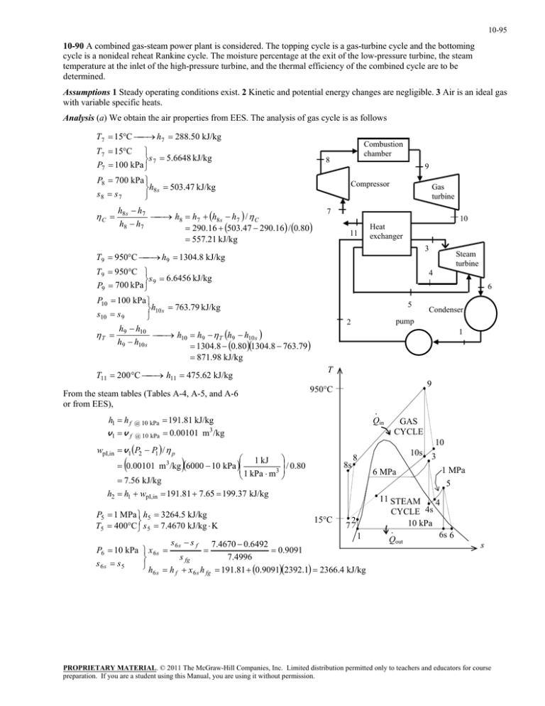
10-95 10-90 A combined gas-steam power plant is considered. The topping cycle is a gas-turbine cycle and the bottoming cycle is a nonideal reheat Rankine cycle. The moisture percentage at the exit of the low-pressure turbine, the steam temperature at the inlet of the high-pressure turbine, and the thermal efficiency of the combined cycle are to be determined. Assumptions 1 Steady operating conditions exist. 2 Kinetic and potential energy changes are negligible. 3 Air is an ideal gas with variable specific heats. Analysis (a) We obtain the air properties from EES. The analysis of gas cycle is as follows h7 288.50 kJ/kg T7 15C T7 15C s 7 5.6648 kJ/kg P7 100 kPa P8 700 kPa h8 s 503.47 kJ/kg s8 s 7 C Combustion chamber 8 9 Compressor h8 s h7 h8 h7 h8 s h7 / C h8 h7 290.16 503.47 290.16 / 0.80 557.21 kJ/kg Gas turbine 7 11 10 Heat exchanger 3 h9 1304.8 kJ/kg T9 950C T9 950C s 9 6.6456 kJ/kg P9 700 kPa Steam turbine 4 6 P10 100 kPa h10 s 763.79 kJ/kg s10 s 9 h h T 9 10 h10 h9 T h9 h10 s h9 h10 s 1304.8 0.80 1304.8 763.79 5 Condenser pump 2 1 871.98 kJ/kg h11 475.62 kJ/kg T11 200 C From the steam tables (Tables A-4, A-5, and A-6 or from EES), h1 h f v1 v f @ 10 kPa @ 10 kPa 9 950C · Qin 191.81 kJ/kg 0.00101 m3 /kg wpI,in v1 P2 P1 / p T 10 1 kJ / 0.80 0.00101 m 3 /kg 6000 10 kPa 1 kPa m 3 7.56 kJ/kg 8s P6 10 kPa x 6 s s 6s s5 h 6s 6 MPa 3 1 MPa 5 15C 7 2 1 7.4670 0.6492 0.9091 s fg 7.4996 h f x 6 s h fg 191.81 0.90912392.1 2366.4 kJ/kg s 6s s f 10s 8 h2 h1 wpI,in 191.81 7.65 199.37 kJ/kg P5 1 MPa h5 3264.5 kJ/kg T5 400C s 5 7.4670 kJ/kg K GAS CYCLE 11 STEAM 4 CYCLE 4s 10 kPa · 6s 6 Qout s PROPRIETARY MATERIAL. © 2011 The McGraw-Hill Companies, Inc. Limited distribution permitted only to teachers and educators for course preparation. If you are a student using this Manual, you are using it without permission. 10-96 T h5 h6 h6 h5 T h5 h6 s h5 h6 s 3264.5 0.80 3264.5 2366.4 2546.0 kJ/kg P6 10 kPa x 0.9842 h6 2546.5 kJ/kg 6 Moisture Percentage 1 x 6 1 0.9842 0.0158 1.6% (b) Noting that Q W Δke Δpe 0 for the heat exchanger, the steady-flow energy balance equation yields E in E out m h m h i i e e m s h3 h2 m s h5 h4 m air h10 h11 (1.15)(3346.5 199.37) (3264.5 h4 ) (10)(871.98 475.62) h4 2965.0 kJ/kg Also, P3 6 MPa h3 T3 ? s3 T P4 1 MPa h4 s s 4s s3 h3 h4 h4 h3 T h3 h4 s h3 h4 s The temperature at the inlet of the high-pressure turbine may be obtained by a trial-error approach or using EES from the above relations. The answer is T3 = 468.0ºC. Then, the enthalpy at state 3 becomes: h3 = 3346.5 kJ/kg (c) W T,gas m air h9 h10 10 kg/s 1304.8 871.98 kJ/kg 4328 kW W C,gas m air h8 h7 10 kg/s 557.21 288.50 kJ/kg 2687 kW W net,gas W T,gas W C,gas 4328 2687 1641 kW W T,steam m s h3 h4 h5 h6 1.15 kg/s 3346.5 2965.0 3264.5 2546.0 kJ/kg 1265 kW W P,steam m s w pump 1.15 kg/s 7.564 kJ/kg 8.7 kW W net,steam W T,steam W P,steam 1265 8.7 1256 kW W net,plant W net,gas W net,steam 1641 1256 2897 kW (d) Q in m air h9 h8 10 kg/s 1304.8 557.21 kJ/kg 7476 kW th W net,plant 2897 kW 0.388 38.8% 7476 kW Q in PROPRIETARY MATERIAL. © 2011 The McGraw-Hill Companies, Inc. Limited distribution permitted only to teachers and educators for course preparation. If you are a student using this Manual, you are using it without permission.
