sketched and the temperature and pressure at the exit of... 9-102
advertisement
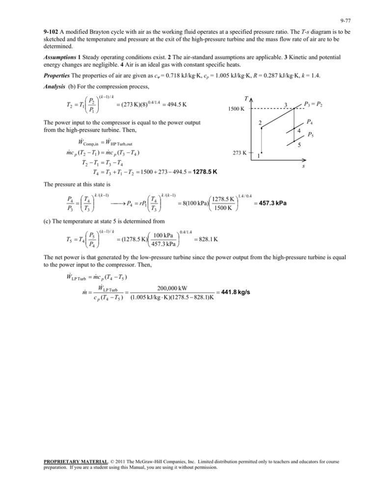
9-77 9-102 A modified Brayton cycle with air as the working fluid operates at a specified pressure ratio. The T-s diagram is to be sketched and the temperature and pressure at the exit of the high-pressure turbine and the mass flow rate of air are to be determined. Assumptions 1 Steady operating conditions exist. 2 The air-standard assumptions are applicable. 3 Kinetic and potential energy changes are negligible. 4 Air is an ideal gas with constant specific heats. Properties The properties of air are given as cv = 0.718 kJ/kg·K, cp = 1.005 kJ/kg·K, R = 0.287 kJ/kg·K, k = 1.4. Analysis (b) For the compression process, P T2 T1 2 P1 ( k 1) / k T (273 K)(8) 0.4/1.4 494.5 K The power input to the compressor is equal to the power output from the high-pressure turbine. Then, P3 = P2 3 1500 K P4 2 4 W Comp,in W HP Turb,out P5 5 m c p (T2 T1 ) m c p (T3 T4 ) 273 K T2 T1 T3 T4 1 s T4 T3 T1 T2 1500 273 494.5 1278.5 K The pressure at this state is P4 T4 P3 T3 k /( k 1) T P4 rP1 4 T3 k /( k 1) 1278.5 K 8(100 kPa) 1500 K 1.4 / 0.4 457.3 kPa (c) The temperature at state 5 is determined from P T5 T4 5 P4 ( k 1) / k 100 kPa (1278.5 K) 457.3 kPa 0.4/1.4 828.1 K The net power is that generated by the low-pressure turbine since the power output from the high-pressure turbine is equal to the power input to the compressor. Then, W LP Turb m c p (T4 T5 ) m W LP Turb 200,000 kW 441.8 kg/s c p (T4 T5 ) (1.005 kJ/kg K )(1278.5 828.1)K PROPRIETARY MATERIAL. © 2011 The McGraw-Hill Companies, Inc. Limited distribution permitted only to teachers and educators for course preparation. If you are a student using this Manual, you are using it without permission.
