Differential Relations for Fluid Flow
advertisement

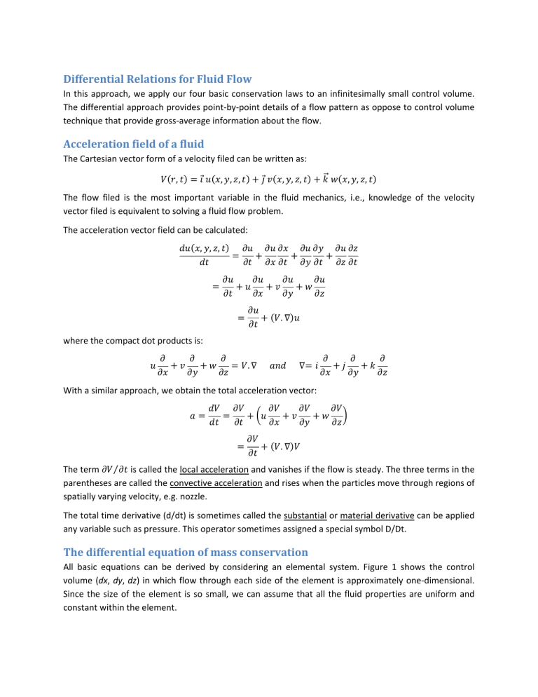
Differential Relations for Fluid Flow In this approach, we apply our four basic conservation laws to an infinitesimally small control volume. The differential approach provides point‐by‐point details of a flow pattern as oppose to control volume technique that provide gross‐average information about the flow. Acceleration field of a fluid The Cartesian vector form of a velocity filed can be written as: , , , , , , , , , , The flow filed is the most important variable in the fluid mechanics, i.e., knowledge of the velocity vector filed is equivalent to solving a fluid flow problem. The acceleration vector field can be calculated: , , , . where the compact dot products is: . With a similar approach, we obtain the total acceleration vector: . The term ⁄ is called the local acceleration and vanishes if the flow is steady. The three terms in the parentheses are called the convective acceleration and rises when the particles move through regions of spatially varying velocity, e.g. nozzle. The total time derivative (d/dt) is sometimes called the substantial or material derivative can be applied any variable such as pressure. This operator sometimes assigned a special symbol D/Dt. The differential equation of mass conservation All basic equations can be derived by considering an elemental system. Figure 1 shows the control volume (dx, dy, dz) in which flow through each side of the element is approximately one‐dimensional. Since the size of the element is so small, we can assume that all the fluid properties are uniform and constant within the element. Fig.1: Fixed Cartesian element showing inlet and outlet flows on the x‐direction. The conservation of mass for the element can be written as: 0 After dividing by the volume of the element: . 0 Fig. 2: Cylindrical polar coordinate. The continuity equation for the cylindrical polar coordinates is: 1 1 where velocity vector , , 0 . For steady compressible flow, continuity equation simplifies to: M. Bahrami Fluid Mechanics (S 09) Differential Relations for Fluid Flow 2 , 0 1 1 , 0 For incompressible flow, continuity equation can be further simplified since density changes are negligible: . 0 , , 0 1 1 A flow can be considered incompressible when 0 0.3. Note: the continuity equation is always important and must always be satisfied for a rational analysis of a flow pattern. The differential equation of linear momentum In a Cartesian coordinates, the momentum equation can be written as: There are types of forces: body forces and surface forces. Body forces are due to external fields such as gravity and magnetism fields. We only consider gravity forces: The surface forces are due to the stresses on the sides of the control surface. These stresses are the sum which arise from the motion of the fluid: of hydrostatic pressure plus viscous stresses Unlike velocity, stresses and strains are nine‐component tensors and require two subscripts to define each component. The net surface force due to stresses in the x‐direction can be found as: , M. Bahrami Fluid Mechanics (S 09) Differential Relations for Fluid Flow 3 Fig.2: stress tensor. Similarly we can find the net surface force in y and z direction. After summing them up and dividing through by the volume, we get: . Note: the surface force is the sum of the pressure gradient and the divergence of the viscous stress tensor. Therefore the linear momentum equation for an infinitesimal element becomes: . where This is a vector equation, and can be written as: M. Bahrami Fluid Mechanics (S 09) Differential Relations for Fluid Flow 4 Special cases of momentum equation: Inviscid flow: Euler’s equation When the viscous terms are negligible, i.e. 0 Euler’s equation can be integrated along a streamline to yield the frictionless Bernoulli equation. Newtonian fluid: Navier­Stokes equation For a Newtonian fluid, the viscous stresses are proportional to the element strain rates and the coefficient of viscosity. 2 2 2 where is the viscosity coefficient. Substituting shear stresses in the momentum equation, for a Newtonian fluid with constant density and viscosity, we get: These are the incompressible flow Navier‐stokes equations. Note: Navier‐Stokes equations have four unknowns: p, u, v, and w. They should be combined with the continuity equation to form four equations for theses unknowns. Navier‐Stokes equations have a limited number of analytical solutions; these equations typically are solved numerically using computational fluid dynamics (CFD) software and techniques. The differential equation of angular momentum Application of the integral theorem to a differential element gives that the shear stresses are symmetric: M. Bahrami Fluid Mechanics (S 09) Differential Relations for Fluid Flow 5 Fig. 3: Fixed Cartesian element showing shear stresses that may cause a net angular acceleration about O. Therefore, there is no differential angular momentum equation. The boundary conditions for the basic equations We have 3 differential equations to solve: i) continuity equation, ii) momentum, and iii) energy. Typically, the density is variable, so the three equations contain 5 unknowns: , , , . Therefore, we need 2 additional relations to complete the system of equations. These are provided by data or algebraic expressions for state relations of thermodynamic properties such as ideal gas equation of state: , For ideal gas, we have: conditions for each variable. ⁄ , . So, we need to set proper, initial and boundary Some important boundary conditions: Tfluid = Twall (no‐temperature jump) At solid wall: Vfluid = Vwall (no‐slip condition) At inlet or outlet section of the flow: V, p, T are known At a liquid‐gas interface: equality of vertical velocity across the interface (kinematic boundary condition). Mechanical equilibrium at liquid‐gas interface, and At a liquid‐gas interface: heat transfer must be the same, M. Bahrami Fluid Mechanics (S 09) , or Differential Relations for Fluid Flow 6 Incompressible flow with constant properties Flow with constant , , leads to: is a basic simplification that is very common in engineering problem that . Continuity 0 Momentum For frictionless or inviscid flows in which 0. The momentum equation reduces to Euler’s equation: Some illustrative incompressible viscous flows Couette flow between a fixed and a moving plate Consider two‐dimensional incompressible plane viscous flow between parallel plates, 0, a distance 2h apart, as shown in Fig. 4. We assume that the plates are very wide and very long and that the flow is essentially axial. 0 0 Fig. 4: Incompressible viscous flow between parallel plates, a) no pressure gradient; b) pressure gradient with both plates fixed. From continuity equation, we learn: 0 0 We neglect gravity effects and assume fully‐developed flow. Substitute equation for x‐direction: M. Bahrami Fluid Mechanics (S 09) in the Navier‐Stokes Differential Relations for Fluid Flow 7 After simplifications, it reduces to: 0 We need two boundary conditions to find the constants C1 and C2. At y=+h, u = V =C1h + C2 At y= ‐ h, u = 0 = C1 (‐h) +C2 Therefore, the solution for flow between plates with a moving upper wall is: 2 2 This is called Couette flow due to a moving wall: a linear velocity profile with no slip at each wall. Couette flow due to pressure gradient between two fixed plates Let’s consider case (b) in Fig. 4, where both plates are fixed but pressure varies in the x‐direction. If 0, the continuity equation lead to the same result, namely: The x‐momentum equation changes because the pressure is variable: Also, since 0 and gravity is neglected, the y and z momentum equations lead to: 0 0 Thus, the pressure gradient in x‐direction is the only and total gradient: 0 The solution is accomplished by double integration: M. Bahrami Fluid Mechanics (S 09) Differential Relations for Fluid Flow 8 1 2 The constants can be found from the no‐slip boundary condition at the walls: at : 0 Thus, C1= 0 and . The velocity distribution in a channel due to pressure gradient is: 2 1 The flow forms a Poiseuille parabola of constant negative curvature, where the maximum velocity occurs at the center. Fully‐developed laminar pipe flow This is one of the most useful exact solutions to the Navier‐Stokes equation: fully‐developed incompressible flow in straight circular pipe of radius R. Fully‐developed flow: refers to the flow in a region far enough from the entrance that the flow is purely axial. As a result, the velocity distribution in the tube is fixed (not changing along the tube). 0 Neglecting gravity effects and assuming axial symmetry, i.e., 0, the continuity equation in cylindrical coordinates, reduces to: 1 1 0 It means that the flow proceeds straight down the pipe without radial motion. The r‐momentum equation in cylindrical coordinates, simplifies to 0 only. The z‐momentum equation in cylindrical coordinates, reduces to: 1 1 0 This equation is linear and can be integrated twice: 4 ln Applying, the no‐slip boundary condition at the wall and finite velocity at the centerline, gives us: M. Bahrami Fluid Mechanics (S 09) Differential Relations for Fluid Flow 9 0 ln Finite velocity at r = 0: 0 No‐slip at r = R: ln 0 0 The final solution for fully‐developed Hagen‐Poiseuille flow is: 1 4 The velocity profile is a paraboloid with a maximum at the centerline. Flow between long concentric cylinders Consider an incompressible flow between two concentric cylinders, as shown in Fig. 5. There is no axial ⁄ motion or end effect, 0. Fig. 5: Incompressible viscous flow between long cylinders. The continuity, with 0, reduces: 1 1 0 . Note that does not vary with . Also since 0 at both the inner and outer cylinders, it follows 0 everywhere, as a result, the motion will be purely circumferential, . The that momentum equation in direction is: . 1 In cylindrical coordinates, we have: M. Bahrami Fluid Mechanics (S 09) Differential Relations for Fluid Flow 10 1 As a result, the momentum equation becomes: 0 This is a linear 2nd order ordinary differential equation: The constants can be found by applying boundary conditions: At r = ro: 0 At r = ri: Ω ⁄ ⁄ The final solution for the velocity distribution is: Ω M. Bahrami Fluid Mechanics (S 09) Differential Relations for Fluid Flow 11


