U
advertisement
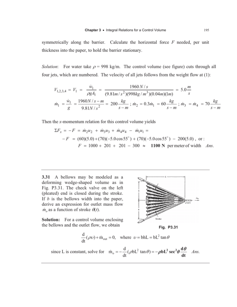
Chapter 3 x Integral Relations for a Control Volume symmetrically along the barrier. 195 Calculate the horizontal force F needed, per unit thickness into the paper, to hold the barrier stationary. Solution: For water take U = 998 kg/m. The control volume (see figure) cuts through all four jets, which are numbered. The velocity of all jets follows from the weight flow at (1): V1, 2,3,4 m 1 w 1 UgA1 V1 w 1 g 1960 N / s (9.81m / s 2 )(998kg / m 3 )(0.04m)(1m) 1960 N / s m 9.81N / s 2 200 kg ; m 2 sm 0.3m 1 60 5.0 kg ; m 3 sm m s m 4 70 kg sm Then the x-momentum relation for this control volume yields 6Fx m 2 u 2 m 3u3 m 4 u 4 m 1u1 F F (60)(5.0) (70)(5.0 cos 55D ) (70)(5.0 cos 55D ) 200(5.0) , or : F 1000 201 201 300 | 1100 N per meter of width 3.31 A bellows may be modeled as a deforming wedge-shaped volume as in Fig. P3.31. The check valve on the left (pleated) end is closed during the stroke. If b is the bellows width into the paper, derive an expression for outlet mass flow m o as a function of stroke T(t). Solution: For a control volume enclosing the bellows and the outlet flow, we obtain d out ( UX ) m dt 0, where X o since L is constant, solve for m Fig. P3.31 bhL bL2 tan T d dT ( U bL2 tan T ) U bL2 sec 2T dt dt Ans. Ans.
