Fluid Mechanics: Boundary Layer & Shear Stress Examples
advertisement
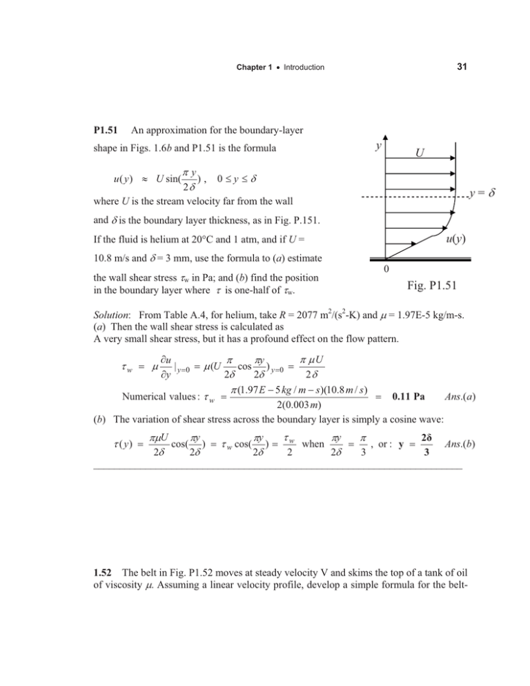
31 Chapter 1 x Introduction P1.51 An approximation for the boundary-layer shape in Figs. 1.6b and P1.51 is the formula u ( y ) | U sin( y U Sy ), 0dy dG 2G y=G where U is the stream velocity far from the wall and G is the boundary layer thickness, as in Fig. P.151. u(y) If the fluid is helium at 20qC and 1 atm, and if U = 10.8 m/s and G = 3 mm, use the formula to (a) estimate the wall shear stress Ww in Pa; and (b) find the position in the boundary layer where W is one-half of Ww. 0 Fig. P1.51 Solution: From Table A.4, for helium, take R = 2077 m2/(s2-K) and P = 1.97E-5 kg/m-s. (a) Then the wall shear stress is calculated as A very small shear stress, but it has a profound effect on the flow pattern. Ww P wu |y wy 0 P (U Numerical values : W w S PU S Sy cos ) y 0 2G 2G 2G S (1.97 E 5 kg / m s)(10.8 m / s ) 0.11 Pa Ans.(a) 2(0.003 m) (b) The variation of shear stress across the boundary layer is simply a cosine wave: Ww Sy S Sy 2 SPU Sy cos( ) W w cos( ) when , or : y Ans.(b) 3 2G 2G 2G 2 2G 3 _______________________________________________________________________ W ( y) 1.52 The belt in Fig. P1.52 moves at steady velocity V and skims the top of a tank of oil of viscosity P. Assuming a linear velocity profile, develop a simple formula for the belt-


![The streamlines are logarithmic spirals moving out from the origin. ... about O.] This simple distribution is often used to...](http://s2.studylib.net/store/data/012446347_1-856dfe1450220540b95d56f386c12aa6-300x300.png)

