EM 424 Spring 2009 Adv.Mech. Mat.
advertisement
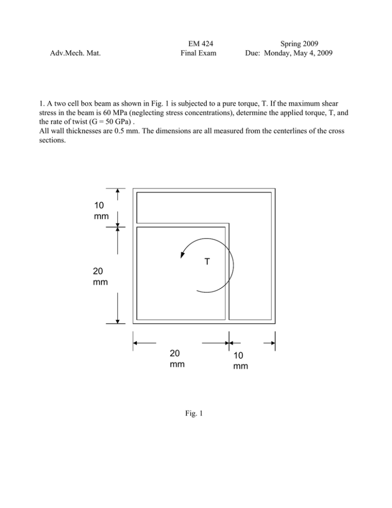
Adv.Mech. Mat. EM 424 Final Exam Spring 2009 Due: Monday, May 4, 2009 1. A two cell box beam as shown in Fig. 1 is subjected to a pure torque, T. If the maximum shear stress in the beam is 60 MPa (neglecting stress concentrations), determine the applied torque, T, and the rate of twist (G = 50 GPa) . All wall thicknesses are 0.5 mm. The dimensions are all measured from the centerlines of the cross sections. 10 mm T 20 mm 20 mm 10 mm Fig. 1 2. Consider a triangular retaining wall subject to a hydrostatic pressure from the surrounding soil that varies linearly with depth: x x = y tan β β p =γ y L y Fig. 2 Using an Airy stress function: a b c d φ = x 3 + x 2 y + xy 2 + y 3 6 2 2 6 (a) Find the constants a, b, c, d that satisfy this problem and the stresses in the wall in terms of x and y. Neglect the weight of the wall. Hint: on the inclined edge of the wall it is easier to consider the boundary conditions on the xand y-components of the stress vector than on the normal and tangential stress components. (b) Draw the normal and shear stress distributions at the base ( y = L) (c) Show that Saint Venant's conditions are satisfied at the base. 3. The box beam shown in Fig. 3 ( Iyy = 687.5x106 mm4) supports a vertical shear force Vz = 10 kN acting through its shear center. Determine the location of the shear center (the distance, e, as shown) and show on a sketch the complete shear flow distributions. All distances are measured from the centerlines of the cross-section. z 300 mm 20 mm y e 500 mm Vz 10 mm all around except for the left Fig. 3 4. The cantilever beam shown in Fig. 4 has an angle cross section of the dimensions shown. (distances are not measured to the centerlines here). the load P acts through the shear center. At the fixed support, determine the maximum tensile and compressive flexural stresses (and their location in the cross section) and the angle that the neutral axis makes with the y-axis. z x y 4.0 in. 60.0 in. 2.0 in. o 15 thickness = 0.1 in for entire section P = 60 lb Fig. 4


