Turbulent Flow and Transport References: Thermal performance of
advertisement
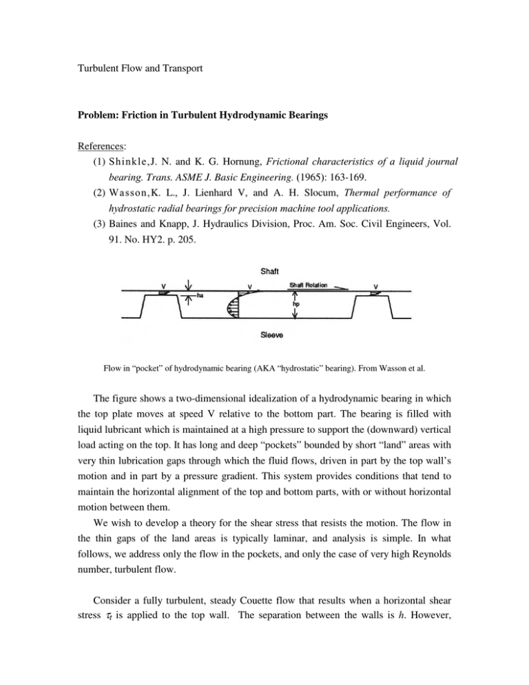
Turbulent Flow and Transport Problem: Friction in Turbulent Hydrodynamic Bearings References: (1) Shinkle,J. N. and K. G. Hornung, Frictional characteristics of a liquid journal bearing. Trans. ASME J. Basic Engineering. (1965): 163-169. (2) Wasson,K. L., J. Lienhard V, and A. H. Slocum, Thermal performance of hydrostatic radial bearings for precision machine tool applications. (3) Baines and Knapp, J. Hydraulics Division, Proc. Am. Soc. Civil Engineers, Vol. 91. No. HY2. p. 205. Flow in “pocket” of hydrodynamic bearing (AKA “hydrostatic” bearing). From Wasson et al. The figure shows a two-dimensional idealization of a hydrodynamic bearing in which the top plate moves at speed V relative to the bottom part. The bearing is filled with liquid lubricant which is maintained at a high pressure to support the (downward) vertical load acting on the top. It has long and deep “pockets” bounded by short “land” areas with very thin lubrication gaps through which the fluid flows, driven in part by the top wall’s motion and in part by a pressure gradient. This system provides conditions that tend to maintain the horizontal alignment of the top and bottom parts, with or without horizontal motion between them. We wish to develop a theory for the shear stress that resists the motion. The flow in the thin gaps of the land areas is typically laminar, and analysis is simple. In what follows, we address only the flow in the pockets, and only the case of very high Reynolds number, turbulent flow. Consider a fully turbulent, steady Couette flow that results when a horizontal shear stress τt is applied to the top wall. The separation between the walls is h. However, because of boundary conditions far upstream or far downstream of a station x (the pressure drop across the land areas is high), the net volume flow rate at any station is essentially zero. The steady state must therefore be one where a horizontal pressure gradient p/ x has been set up and the magnitude of the gradient has adjusted itself so that the leftward volume flow rate near the bottom exactly balances the rightward volume flow rate near the top, and Q=0. We assume that the channel length is so large compared with h that the flow can be considered fully developed ( / x=0 except for pressure). Our objective is to derive the mean velocity distribution in this flow in the reference frame where the bottom wall is stationary, based on the assumption that the turbulent kinematic viscosity νT in much of the flow can be approximated by the very simple relationship 1 1 1 = + ν T κut (h − y) κub y where (1) ut = τ t / ρ = friction velocity applied at the top wall ub = τ b / ρ = friction velocity which results at the bottom wall, τt and τb being the absolute magnitudes of the shear stresses on the top and bottom walls, respectively. The given quantities are: ut (or the shear stress τt) applied at the top, y=h, and the fluid properties. In addition, we assume that the two walls are of identical material and possess the same value of the function ∆C(k + ) that characterizes the effect of wall roughness on the logarithmic portion of the law of the wall. This will render the results applicable to both smooth and rough walls. The friction velocity ub at the bottom wall is not known a priori, but must be determined. Our aim is to obtain (i) the mean-velocity profile and (ii) the speed V of the top wall in terms of the given quantities. (a) In what regions of the flow do you expect equation (1) to be a good approximation, a fair approximation, or inapplicable? Explain. (b) What is the relationship between the pressure gradient and the shear stresses (shear velocities) at the top and bottom walls? (c) Obtain a solution for the mean speed u(y) in this flow outside the viscous sublayers. A convenient way to proceed is to first find the solution in the form u = f (z,Reτ ,∆C,n) ut (2) where y uh u z = , Reτ = τ , and n = b ut h ν (3) and then apply a boundary condition to obtain a relationship between n=τb/τt and Reτ. (Note: This will turn out to be an implicit equation for n(Reτ), but you can obtain Reτ as a function of n explicitly.) You may simplify your result by using approximations that are appropriate in the limit of very large Reτ. Explain clearly how you deal with the boundary conditions in obtaining this solution. (Caution: note that the direction of the flow in the inner layer over the bottom wall is leftward and also that the usual form of the law of the wall is expressed in the reference frame of the wall.) (d) Obtain an expression for the mean flow speed V at the top surface, i.e. at y=h. (e) Figure 9 of Shinkle and Hornung provides experimental data for fp vs Re, where fp = τt ρVh , Re = 2 0.5 ρV µ (4) Compare your solution with these data. *** For experimental data on the velocity distribution, see the study by Baines and Knapp of a similar flow field set up by wind-driven water currents.
