For ConTech Lighting Compact Fluorescent Dimmable Pendants (CMCFPL Series)
advertisement

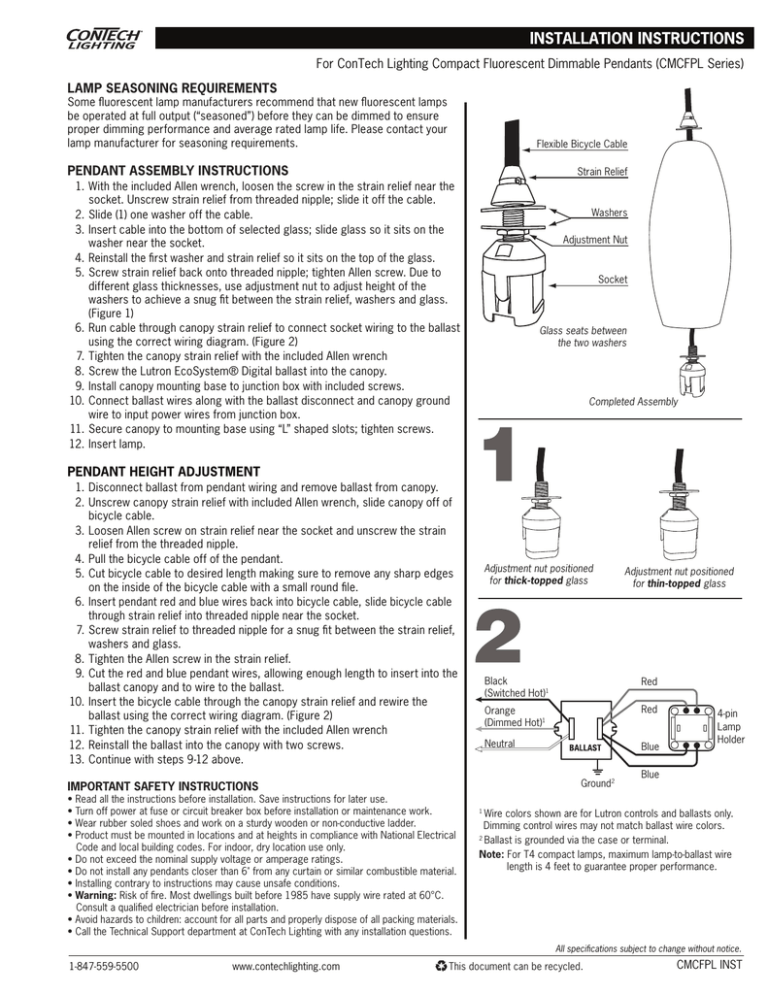
For ConTech Lighting Compact Fluorescent Dimmable Pendants (CMCFPL Series) LAMP SEASONING REQUIREMENTS Some fluorescent lamp manufacturers recommend that new fluorescent lamps be operated at full output (“seasoned”) before they can be dimmed to ensure proper dimming performance and average rated lamp life. Please contact your lamp manufacturer for seasoning requirements. Flexible Bicycle Cable PENDANT ASSEMBLY INSTRUCTIONS Strain Relief 1. With the included Allen wrench, loosen the screw in the strain relief near the socket. Unscrew strain relief from threaded nipple; slide it off the cable. 2. Slide (1) one washer off the cable. 3. Insert cable into the bottom of selected glass; slide glass so it sits on the washer near the socket. 4. Reinstall the first washer and strain relief so it sits on the top of the glass. 5. Screw strain relief back onto threaded nipple; tighten Allen screw. Due to different glass thicknesses, use adjustment nut to adjust height of the washers to achieve a snug fit between the strain relief, washers and glass. (Figure 1) 6. Run cable through canopy strain relief to connect socket wiring to the ballast using the correct wiring diagram. (Figure 2) 7. Tighten the canopy strain relief with the included Allen wrench 8. Screw the Lutron EcoSystem® Digital ballast into the canopy. 9. Install canopy mounting base to junction box with included screws. 10. Connect ballast wires along with the ballast disconnect and canopy ground wire to input power wires from junction box. 11. Secure canopy to mounting base using “L” shaped slots; tighten screws. 12. Insert lamp. Washers Adjustment Nut Socket Glass seats between the two washers Completed Assembly PENDANT HEIGHT ADJUSTMENT 1. Disconnect ballast from pendant wiring and remove ballast from canopy. 2. Unscrew canopy strain relief with included Allen wrench, slide canopy off of bicycle cable. 3. Loosen Allen screw on strain relief near the socket and unscrew the strain relief from the threaded nipple. 4. Pull the bicycle cable off of the pendant. 5. Cut bicycle cable to desired length making sure to remove any sharp edges on the inside of the bicycle cable with a small round file. 6. Insert pendant red and blue wires back into bicycle cable, slide bicycle cable through strain relief into threaded nipple near the socket. 7. Screw strain relief to threaded nipple for a snug fit between the strain relief, washers and glass. 8. Tighten the Allen screw in the strain relief. 9. Cut the red and blue pendant wires, allowing enough length to insert into the ballast canopy and to wire to the ballast. 10. Insert the bicycle cable through the canopy strain relief and rewire the ballast using the correct wiring diagram. (Figure 2) 11. Tighten the canopy strain relief with the included Allen wrench 12. Reinstall the ballast into the canopy with two screws. 13. Continue with steps 9-12 above. Adjustment nut positioned for thick-topped glass Black (Switched Hot)1 Red Orange (Dimmed Hot)1 Red Neutral Blue Ground2 IMPORTANT SAFETY INSTRUCTIONS • Read all the instructions before installation. Save instructions for later use. • Turn off power at fuse or circuit breaker box before installation or maintenance work. • Wear rubber soled shoes and work on a sturdy wooden or non-conductive ladder. • Product must be mounted in locations and at heights in compliance with National Electrical Code and local building codes. For indoor, dry location use only. • Do not exceed the nominal supply voltage or amperage ratings. • Do not install any pendants closer than 6" from any curtain or similar combustible material. • Installing contrary to instructions may cause unsafe conditions. • Warning: Risk of fire. Most dwellings built before 1985 have supply wire rated at 60°C. Consult a qualified electrician before installation. • Avoid hazards to children: account for all parts and properly dispose of all packing materials. • Call the Technical Support department at ConTech Lighting with any installation questions. Adjustment nut positioned for thin-topped glass 4-pin Lamp Holder Blue Wire colors shown are for Lutron controls and ballasts only. Dimming control wires may not match ballast wire colors. 2 Ballast is grounded via the case or terminal. Note: For T4 compact lamps, maximum lamp-to-ballast wire length is 4 feet to guarantee proper performance. 1 All specifications subject to change without notice. 1-847-559-5500 www.contechlighting.com This document can be recycled. CMCFPL INST


