Lab Information
advertisement
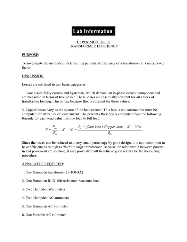
Lab Information EXPERIMENT NO. 5 TRANSFORMER EFFICIENCY PURPOSE: To investigate the methods of determining percent of efficiency of a transformer at a unity power factor. DISCUSSION: Losses are confined to two basic categories: 1. Core losses-Eddy current and hysteresis, which demand an in-phase current component and are measured in terms of true power. These losses are essentially constant for all values of transformer loading. This is true because flux is constant for these values. 2. Copper losses-vary as the square of the load current. This loss is not constant but must be computed for all values of load current. The percent efficiency is computed from the following formula for each load value from no load to full load: Since the losses can be reduced to a very small percentage by good design, it is not uncommon to have efficiencies as high as 98-99 in large transformer. Because the relationship between powerin and power-out are so close, it may prove difficult to achieve good results for the measuring procedure. APPARATUS REQUIRED: 1. One Hampden transformer (T-100-3A) 2. One Hampden RLX-100 resistance-reactance load 3. Two Hampden Wattmeters 4. Two Hampden AC ammeters 5. One Hampden AC voltmeter 6. One Portable AC voltmeter 7. One 208 volt single phase power source PROCEDURE: 1. Make the connections shown in figure 9. Apply a (unity power factor) 333 load to the transformer and record all the meter readings. Increase the load in five steps to the maximum value (2000) and record all the meter readings for each step. 2. Calculate the percent of efficiency using the measured data. 3. Calculate the percent efficiency, using the open circuit test and short circuit test data, for each load applied in step 1 of this procedure. Record these calculations. REPORT: Prepare a written report to include the following items: 1. Calculations for step 1. 2. Circuit schematic. 3. Tables of calculated at measured value. 4. Calculations for step 3. 5. Comparison of methods used in step 1 and 3. 6. Plots of secondary voltage and E as abcissas, versus the secondary current as ordinate for both steps 1 and 3.
