Lab Information
advertisement
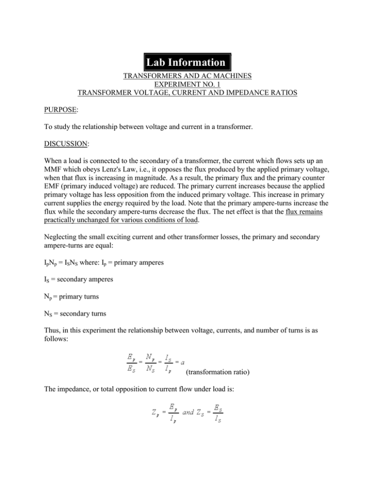
Lab Information TRANSFORMERS AND AC MACHINES EXPERIMENT NO. 1 TRANSFORMER VOLTAGE, CURRENT AND IMPEDANCE RATIOS PURPOSE: To study the relationship between voltage and current in a transformer. DISCUSSION: When a load is connected to the secondary of a transformer, the current which flows sets up an MMF which obeys Lenz's Law, i.e., it opposes the flux produced by the applied primary voltage, when that flux is increasing in magnitude. As a result, the primary flux and the primary counter EMF (primary induced voltage) are reduced. The primary current increases because the applied primary voltage has less opposition from the induced primary voltage. This increase in primary current supplies the energy required by the load. Note that the primary ampere-turns increase the flux while the secondary ampere-turns decrease the flux. The net effect is that the flux remains practically unchanged for various conditions of load. Neglecting the small exciting current and other transformer losses, the primary and secondary ampere-turns are equal: IpNp = ISNS where: Ip = primary amperes IS = secondary amperes Np = primary turns NS = secondary turns Thus, in this experiment the relationship between voltage, currents, and number of turns is as follows: (transformation ratio) The impedance, or total opposition to current flow under load is: It can be shown that: APPARATUS REQUIRED: 1. One Hampden Transformer (Model T-100-3A) 2. One Hampden RLC-100 Resistance-Reactance Load 3. One Hampden Resistance Load 4. Two Hampden AC ammeters 5. One Hampden AC voltmeter 6. One Hampden 120 volt fixed AC power supply 7. One portable AC voltmeter (rated at least 75 volts) 8. One portable AC ammeter (rated at least 1 amp) PROCEDURE: 1. Make the connections shown in figure 1. Apply approximately 0.4 amperes resistive load (333Ω) to the secondary of the transformer using the Hampden Resistive Load. Record the primary and secondary voltages and amperes. 2. Calculate the voltage, current, and impedance ratios and record your results. 3. Make the connections shown in figure 2. This is most easily done by first placing an AC ammeter in series with the resistive load of figure 1. Then before connecting the reactance load, apply power to the primary of the transformer. Observe and record the current in the secondary. Divide the secondary current by a power factor of 0.8. Now connect the resistance-reactance load as shown in figure 2. After reapplying power, turn the reactance knob counter-clockwise until the total secondary current equals the value calculated above. This gives a 0.8 lagging power factor load. Record the primary volts and amps. Now apply a 0.8 leading power factor load to the secondary. Record the primary and secondary volts and amps. 4. Calculate the voltage, current, and impedance ratios for the lagging power factor load and then for the leading power factor load. Record the results. 5. Determine the power dissipation, PL of the loads in Steps 1 and 3. QUESTIONS: 1. What load conditions must be met so that a load in the primary side "sees" an impedance match in the secondary? 2. What commercial use is made of impedance transformation? 3. What apparent effect did power factor have on the voltage, current, and impedance ratios? 4. Explain the reason for the difference between the secondary voltage obtained for the inductive and capacitive loads? Why are the current values equal? REPORT: Prepare a report containing: 1. Diagrams of each circuit. 2. All calculations and required data. 3. An error analysis. 4. Answers to questions.
