Modifications/Changes in this update
advertisement
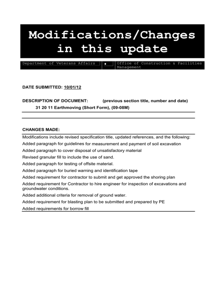
Modifications/Changes in this update Department of Veterans Affairs ♦ Office of Construction & Facilities Management DATE SUBMITTED: 10/01/12 DESCRIPTION OF DOCUMENT: (previous section title, number and date) 31 20 11 Earthmoving (Short Form), (09-08M) CHANGES MADE: Modifications include revised specification title, updated references, and the following: Added paragraph for guidelines for measurement and payment of soil excavation Added paragraph to cover disposal of unsatisfactory material Revised granular fill to include the use of sand. Added paragraph for testing of offsite material. Added paragraph for buried warning and identification tape Added requirement for contractor to submit and get approved the shoring plan Added requirement for Contractor to hire engineer for inspection of excavations and groundwater conditions. Added additional criteria for removal of ground water. Added requirement for blasting plan to be submitted and prepared by PE Added requirements for borrow fill 10-01-12 SECTION 31 20 11 EARTHWORK (SHORT FORM) SPEC WRITER NOTES: 1. Use this section for small projects where earthwork is not extensive and site work restoration only is required. 2. Where materials are specified, substitute readily available materials meeting local State DOT standards, if possible. Contact local quarries regarding availability of local materials meeting State DOT standards. 3. Delete between // ---- // if not applicable to project. Also delete any other item or paragraph not applicable in the section and renumber the paragraphs. PART 1 - GENERAL 1.1:DESCRIPTION: This section specifies the requirements for furnishing all equipment, materials, labor and techniques for earthwork including excavation, fill, backfill and site restoration utilizing fertilizer, seed and/or sod. 1.2 DEFINITIONS: A. Unsuitable Materials: 1. Fills: Topsoil, frozen materials; construction materials and materials subject to decomposition; clods of clay and stones larger than 75 mm (3 inches); organic materials, including silts, which are unstable; and inorganic materials, including silts, too wet to be stable. 2. Existing Subgrade (except footings): Same materials as above paragraph, that are not capable of direct support of slabs, pavement, and similar items, with the possible exception of improvement by compaction, proofrolling, or similar methods of improvement. 3. Existing Subgrade (footings only): Same as Paragraph 1, but no fill or backfill. If materials differ from // reference borings and // design requirements, excavate to acceptable strata subject to Resident Engineer's approval. B. Earthwork: Earthwork operations required within the new construction area. It also includes earthwork required for auxiliary structures and buildings and sewer and other trenchwork throughout the job site. C. Degree of Compaction: Degree of compaction is expressed as a percentage of maximum density obtained by the test procedure presented in // AASHTO // T99 // T180 // Method A. // ASTM // D698 // D1557 // Method A. // D. The term fill means fill or backfill as appropriate. 31 20 11 - 2 10-01-12 1.3 RELATED WORK: A. Materials testing and inspection during construction: Section 01 45 29, TESTING LABORATORY SERVICES. B. Safety Requirements // and blasting operations //: Section 00 72 00, GENERAL CONDITIONS, Article, ACCIDENT PREVENTION. C. Protection of existing utilities, fire protection services, existing equipment, roads, and pavements: Section 01 00 00, GENERAL REQUIREMENTS. D. Subsurface Investigation: Section 01 00 00, GENERAL REQUIREMENTS, Article, PHYSICAL DATA. //E. Foundation System Requirements: Section 31 62 00, DRIVEN PILES, Section 31 63 16, AUGER CAST GROUT PILES, Section 31 63 26, DRILLED CAISSONS, FLOWABLE FILL, Section 31 23 23.33. // 1.4 CLASSIFICATION OF EXCAVATION: A. Unclassified Excavation: Removal and disposal of pavements and other man-made obstructions visible on the surface; utilities, and other items including underground structures indicated to be demolished and removed; together with any type of materials regardless of character of material and obstructions encountered. SPEC WRITER NOTE: Retain either Unclassified excavation above or classified excavation below. B. Classified Excavation: Removal and disposal of all material not defined as rock. C. Rock Excavation: 1. Solid ledge rock (igneous, metamorphic, and sedimentary rock). 2. Bedded or conglomerate deposits so cemented as to present characteristics of solid rock which cannot be excavated without blasting; or the use of a modern power excavator (shovel, backhoe, or similar power excavators) of no less than 0.75 m3 (1 cubic yard) capacity, properly used, having adequate power and in good running condition. 3. Boulders or other detached stones each having a volume of 0.4 m3 (1/2 cubic yard) or more. 1.5 MEASUREMENT AND PAYMENT FOR EXCAVATION: Measurement: The unit of measurement for excavation and borrow will be the cubic yard, computed by the average end area method from cross sections taken before and after the excavation and borrow operations, including the excavation for ditches, gutters, and channel changes, when the material is acceptably utilized or disposed of as herein specified. Quantities should be computed by a Registered Professional Land Surveyor or Registered Civil Engineer, specified in Section 01 00 00, GENERAL 31 20 11 - 3 10-01-12 REQUIREMENTS. //The measurement will include // authorized excavation for rock, // authorized excavation of satisfactory subgrade soil,// and the volume of loose, scattered rocks and boulders collected within the limits of the work; allowance will be made on the same basis for selected backfill ordered as replacement.// The measurement will not include the volume of subgrade material or other material used for purposes other than directed. The volume of overburden stripped from borrow pits and the volume of excavation for ditches to drain borrow its, unless used as borrow material, will not be measured for payment. The measurement will not include the volume of any excavation performed prior to taking of elevations and measurements of the undisturbed grade. 1.6 MEASUREMENT AND PAYMENT FOR ROCK EXCAVATION: A. Measurement: Cross section and measure the uncovered and separated materials, and compute quantities by the Registered Professional Land Surveyor or Registered Civil Engineer, specified in Section 01 00 00, GENERAL REQUIREMENTS. Do not measure quantities beyond the following limits: 1. 300 mm (12 inches) outside of the perimeter of formed footings. 2. 600 mm (24 inches) outside the face of concrete work for which forms are required, except for footings. 3. 150 mm (6 inches) below the bottom of pipe and not more than the pipe diameter plus 600 mm (24 inches) in width for pipe trenches. 4. The outside dimensions of concrete work for which no forms are required (trenches, conduits, and similar items not requiring forms). //B. Payment: No separate payment shall be made for rock excavation quantities shown. The contract price and time will be adjusted for overruns or underruns in accordance with Articles, DIFFERING SITE CONDITIONS, CHANGES and CHANGES-SUPPLEMENT of the GENERAL CONDITIONS as applicable. // //B. Payment for Differing Site Conditions: When rock excavation, as classified, is encountered, the contract price and time will be adjusted in accordance with Articles, DIFFERING SITE CONDITIONS, CHANGES and CHANGES-SUPPLEMENT of the GENERAL CONDITIONS as applicable. // 1.7 SUBMITTALS: A. Submit in accordance with Section 01 33 23, SHOP DRAWINGS, PRODUCT DATA, AND SAMPLES. B. Rock Excavation Report: 1. Certification of rock quantities excavated. 2. Excavation method. 3. Labor. 4. Equipment. 31 20 11 - 4 10-01-12 5. Land Surveyor's or Civil Engineer's name and official registration stamp. 6. Plot plan showing elevations. C. Contractor shall submit procedure and location for disposal of unused satisfactory material. Proposed source of borrow material. Notification of encountering rock in the project. Advance notice on the opening of excavation or borrow areas. Advance notice on shoulder construction for rigid pavements. SPEC WRITER NOTE: Use only when there is a VA Retained Testing Laboratory. D. Furnish to Resident Engineer, soil samples, suitable for laboratory tests, of proposed off site or on site fill material. E. Qualifications of the commercial testing laboratory or Contractor’s Testing facility shall be submitted. 1.8 APPLICABLE PUBLICATIONS: A. Publications listed below form a part of this specification to the extent referenced. Publications are referenced in the text by the basic designation only. B. American Nursery and Landscape Association (ANLA): 2004 ................... American Standard for Nursery Stock C. American Association of State Highway and Transportation Officials (AASHTO): T99-10 ................. Moisture-Density Relations of Soils Using a 2.5 kg (5.5 lb) Rammer and a 305 mm (12 inch) Drop T180-10 ................ Standard Method of Test for Moisture-Density Relations of Soils Using a 4.54-kg [10 lb] Rammer and a 457 mm (18 inch) Drop D. American Society for Testing and Materials (ASTM): C33-03 ................. Concrete Aggregate D698-e1 ................ Laboratory Compaction Characteristics of Soil Using Standard Effort D1140-00 ............... Amount of Material in Soils Finer than the No. 200 (75-micrometer) Sieve D1556-00 ............... Standard Test Method for Density and Unit Weight of Soil in Place by the Sand-Cone Method D1557-09 ............... Laboratory Compaction Characteristics of Soil Using Modified Effort D2167-94 (2001) ........ Standard Test Method for Density and Unit Weight of Soil in Place by the Rubber Balloon Method 31 20 11 - 5 10-01-12 D2487-06 ............... Standard Classification of Soil for Engineering Purposes (Unified Soil Classification System) D6938-10 ............... Standard Test Methods for Density of Soil and Soil-Aggregate in Place by Nuclear Methods (Shallow Depth) E. Standard Specifications of //(Insert name of local state)// State Department of Transportation, latest revision. PART 2 - PRODUCTS 2.1 MATERIALS: SPEC WRITER NOTE: Make material requirements agree with applicable requirements specified in the referenced Applicable Publications. Update and specify only that which applies to the project. A. Fills: Materials approved from on site and off site sources having a minimum dry density of 1760 kg/m3 (110 pcf), a maximum Plasticity Index of 6, and a maximum Liquid Limit of 30. B. Granular Fill: 1. Under concrete slab, granular fill shall consist of clean, poorly graded crushed rock, crushed gravel, or uncrushed gravel placed beneath a building slab with or without a vapor barrier to cut off the capillary flow of pore water to the area immediately below. Fine aggregate grading shall conform to ASTM C33 with a maximum of 3 percent by weight passing ASTM D1140, //75 micrometers (No. 200) sieve//, //or// //37.5 mm (1-1/2 inches)// and no more than 2 percent by weight passing the //4.75 mm (No. 4)// size sieve// //or coarse aggregate Size 57, 67, or 77//. 2. Bedding for sanitary and storm sewer pipe, crushed stone or gravel graded from 13 mm (1/2 inch) to 4.75 mm (No. 4). SPEC WRITER NOTE: Make the following sections match the areas shown on the drawings. Clearly show which areas are to be restored utilizing fertilizer and seed, or sod. Provide a detail in the drawings providing the thickness and condition of the materials to be applied and whether straw is to be applied over the seed. C. Fertilizer: (5-10-5) delivered to site in unopened containers that clearly display the manufacturer's label, indicating the analysis of the contents. D. Seed: Grass mixture comparable to existing turf delivered to site in unopened containers that clearly display the manufacturer's label, indicating the analysis of the contents. 31 20 11 - 6 10-01-12 E. Sod: Comparable species with existing turf. Use State Certified or State Approved sod when available. Deliver sod to site immediately after cutting and in a moist condition. Thickness of cut must be 19 mm to 32 mm (3/4 inch to 1 1/4 inches) excluding top growth. There shall be no broken pads and torn or uneven ends SPEC WRITER NOTE: Include regional requirements for applicable environmental testing of soils to ensure contaminated soils are not imported to the site. The following requirement is that for the State of Virginia. F. Requirements For Offsite Soils: Offsite soils brought in for use as backfill shall be tested for TPH, BTEX and full TCLP including ignitability, corrosivity and reactivity. Backfill shall contain less than //100// parts per million (ppm) of total hydrocarbons (TPH) and less than //10// ppm of the sum of Benzene, Toleune, Ethyl Benzene, and Xylene (BTEX)and shall not fail the TCLP test. TPH concentrations shall be determined by using EPA 600/4-79/020 Method 418.1. BTEX concentrations shall be determined by using EPA SW-846.3-3a Method5030/8020. TCLP shall be performed in accordance with EPA SW- 846.3-3a Method 1311. Provide Borrow Site Testing for TPH, BTEX and TCLP from a composite sample of material from the borrow site, with at least one test from each borrow site. //Material shall not be brought on site until tests have been approved by the Resident Engineer. //G. Buried Warning and Identification Tape: //Polyethylene plastic// //and// //metallic core or metallic-faced, acid- and alkali-resistant polyethylene plastic// warning tape manufactured specifically for warning and identification of buried utility lines. Provide tape on rolls, 3 inch minimum width, color coded as specific below for the intended utility with warning and identification imprinted in bold black letters continuously over the entire tape length. Warning and identification to read, “CAUTION, BURIED (intended service) LINE BELOW” or similar wording. Color and printing shall be permanent, Unaffected by moisture or soil. Warning tape color codes: //Red: Electric// //Yellow: Gas, Oil, Dangerous Materials// //Orange: Telephone and Other Communications// //Blue: Water Systems// //Green: Sewer Systems// //White: Steam Systems// //Gray: Compressed Air// 31 20 11 - 7 10-01-12 H. Warning Tape for Metallic Piping: Acid and alkali-resistant polyethylene plastic tape conforming to the width, color, and printing requirements specified above. mm (0.003 inch). Minimum thickness of tape shall be 0.076 Tape shall have a minimum strength of 10.3 MPa (1500 psi) lengthwise, and 8.6 MPa (1250 psi) crosswise, with a maximum 350 percent elongation. I. Detectable Warning Tape for Non-Metallic Piping: Polyethylene plastictape conforming to the width, color, and printing requirements specified above. Minimum thickness of the tape shall be 0.102 mm (0.004 inch). Tape shall have a minimum strength of 10.3 MPa (1500 psi) lengthwise and 8.6 MPa (1250 psi) crosswise. Tape shall be manufactured with integral wires, foil backing, or other means of enabling detection by a metal detector when tape is buried up to 0.9 m(3 feet) deep. Encase metallic element of the tape in a protective jacket or provide with other means of corrosion protection. J. Detection Wire For Non-Metallic Piping: Detection wire shall be Insulated single strand, solid copper with a minimum of 12 AWG. PART 3 - EXECUTION 3.1 SITE PREPARATION: SPEC WRITER NOTE: Make the following sections match the areas shown on the drawings. Note any visible areas of trash, debris, previously dumped or stored materials to be removed in accordance with these sections on the drawings. NOTE: Do not estimate quantity or volume of materials to be removed if being handled as part of the lump sum price for the work. A. Clearing: Clearing within the limits of earthwork operations as described or designated by the Resident Engineer. Work includes removal of trees, shrubs, fences, foundations, incidental structures, paving, debris, trash and any other obstructions. Remove materials from the // Medical Center // Cemetery Property //. B. Grubbing: Remove stumps and roots 75 mm (3 inches) and larger diameter. Undisturbed sound stumps, roots up to 75 mm (3 inches) diameter, and nonperishable solid objects which will be a minimum of 900 mm (3 feet) below subgrade or finished embankment may be left. // Cemetery Projects: do not leave material within the burial profile up to 2400 mm (8 feet) below finished grade. // C. Trees and Shrubs: Trees and shrubs, not shown for removal, may be removed from the areas within 4500 mm (15 feet) of new construction and 31 20 11 - 8 10-01-12 2250 mm (7’-6”) of utility lines if such removal is approved in advance by the Resident Engineer. Remove materials from the // Medical Center // Cemetery Property //. // Trees and shrubs, shown to be transplanted, shall be dug with a ball of earth and burlapped in accordance with the latest issue of the, "American Standard for Nursery Stock", of the American Association of Nurserymen, Inc. Transplant trees and shrubs to a permanent or temporary position within two hours after digging. Maintain trees and shrubs held in temporary locations by watering as necessary and feeding semi-annually with liquid fertilizer with a minimum analysis of 5 percent nitrogen, 10 percent phosphorus and 5 percent potash. Maintain plants moved to permanent positions as specified for plants in temporary locations until the conclusion of the contract. // Box, and otherwise protect from damage, existing trees and shrubs which are not shown to be removed in the construction area. Repair immediately damage to existing trees and shrubs by trimming, cleaning and painting damaged areas, including the roots, in accordance with standard industry horticultural practice for the geographic area and plant species. Building materials shall not be stored closer to trees and shrubs that are to remain, than the farthest extension of their limbs. D. Stripping Topsoil: Unless otherwise indicated on the drawings, the limits of earthwork operations shall extend anywhere the existing grade is filled or cut or where construction operations have compacted or otherwise disturbed the existing grade or turf. Strip topsoil as defined herein, or as indicated in the geotechnical report, from within the limits of earthwork operations as specified above unless specifically indicated or specified elsewhere in the specifications or shown on the drawings. Topsoil shall be fertile, friable, natural topsoil of loamy character and characteristic of the locality. Topsoil shall be capable of growing healthy horticultural crops of grasses. Stockpile topsoil and protect as directed by the Resident Engineer. Eliminate foreign material, such as weeds, roots, stones, subsoil, frozen clods, and similar foreign materials, larger than 0.014 m3 (1/2 cubic foot) in volume, from soil as it is stockpiled. Retain topsoil on the station. Remove foreign materials larger than 50 mm (2 inches) in any dimension from topsoil used in final grading. Topsoil work, such as stripping, stockpiling, and similar topsoil work, shall not, under any circumstances, be carried out when the soil is wet so that the tilth of the soil will be destroyed. SPEC WRITER NOTE: Modify the specifications for topsoil, whether on 31 20 11 - 9 10-01-12 site or imported to the site, to contain the minimum organic content and constituents identified in the geotechnical report. If there no such recommendations, follow the specifications adopted by the closest State Department of Transportation (DOT) for topsoil. If the onsite topsoil does not meet the minimum requirements of the geotechnical report or DOT standards, whichever is greater, then the soil shall either be amended to meet the requirements, or topsoil shall be imported that does meet the requirements. Edit the specifications or add notes on the drawings requiring that the analysis of the topsoil and plans for achieving the stated constituents and characteristics for the topsoil are submitted to the Resident Engineer for review and approval. //1. Cemetery Projects: Recommend that the top soil be tested for chemicals, pesticides and fertilizers if topsoil is to be removed from lands formerly utilized as farmland, to verify suitability for use as topsoil in the cemetery where new lawn areas are to be established. // 2. Concrete Slabs and Paving: Score deeply or saw cut to insure a neat, straight cut, sections of existing concrete slabs and paving to be removed where excavation or trenching occurs. Extend pavement section to be removed a minimum of 300 mm (12 inches) on each side of widest part of trench excavation and insure final score lines are approximately parallel unless otherwise indicated. Remove material from the // Medical Center // Cemetery Property //. E. Disposal: All materials removed from the property shall be disposed of at a legally approved site, for the specific materials, and all removals shall be in accordance with all applicable Federal, State and local regulations. // No burning of materials is permitted onsite. // 3.2 EXCAVATION: A. Shoring, Sheeting and Bracing: Shore, brace, or slope to it's angle of repose banks of excavations to protect workmen, banks, adjacent paving, structures, and utilities, in compliance with OSHA requirements. 1. Extend shoring and bracing to the bottom of the excavation. Shore excavations that are carried below the elevations of adjacent existing foundations. 2. If the bearing of any foundation is disturbed by excavating, improper shoring or removal of shoring, placing of backfill, and similar operations, provide a concrete fill support // in compliance with Specification Section 31 23 23.33, FLOWABLE FILL, // under disturbed 31 20 11 - 10 10-01-12 foundations, as directed by Resident Engineer, at no additional cost to the Government. Do not remove shoring until permanent work in excavation has been inspected and approved by Resident Engineer. B. Excavation Drainage: Operate pumping equipment //, and/or provide other materials, means and equipment // as required, to keep excavations free of water and subgrades dry, firm, and undisturbed until approval of permanent work has been received from Resident Engineer. // Approval by the Resident Engineer is also required before placement of the permanent work on all subgrades. // When subgrade for foundations has been disturbed by water, remove the disturbed material to firm undisturbed material after the water is brought under control. Replace disturbed subgrade in trenches by mechanically tamped sand or gravel. // When removed disturbed material is located where it is not possible to install and properly compact disturbed subgrade material with mechanically compacted sand or gravel, the Resident Engineer should be contacted to consider the use of flowable fill. // Groundwater flowing toward or into excavations shall be controlled to prevent sloughing of excavation slopes and walls, boils, uplift and heave in the excavation and to eliminate interference with orderly progress of construction. French drains, sumps, ditches or trenches will not be permitted within 0.9 m (3 feet) of the foundation of any structure, except with specific written approval, and after specific contractual provisions for restoration of the foundation area have been made. Control measures shall be taken by the time the excavation reaches the water level in order to maintain the integrity of the in situ material. While the excavation is open, the water level shall be maintained continuously, at least //_____// m (// //feet) below the working level. //Operate dewatering system continuously until construction work below existing water levels is complete. Submit performance records weekly.// //Measure and record performance of dewatering system at same time each day by use of observation wells or piezometers installed in conjunction with the dewatering system.// //Relieve hydrostatic head in pervious zones below subgrade elevation in layered soils to prevent uplift.// SPEC WRITER NOTE: Modify the following paragraph as required for the specific project. Medical Center projects, with occupied facilities, shall not allow blasting. C. Blasting: // Blasting shall be permitted only when authorized by the Resident Engineer. Blasting shall be done with explosives of such quantity and power, and fired in such sequence and locations as to not 31 20 11 - 11 10-01-12 injure personnel, damage or crack rock against which concrete is to be placed, damage property, or damage existing work or other portions of new work. The Contractor shall be responsible for damage caused by blasting operations. //The Contractor shall submit a Blasting Plan, prepared and sealed by a registered professional engineer that includes calculations for overpressure and debris hazard. Blasting mats shall be provided and non-electric blasting caps shall be used. The Contractor shall obtain written approval prior to performing any blasting and shall notify the Resident Engineer 24 hours prior to blasting. The plan shall contain provisions for storing, handling and transporting explosives as well as for the blasting operations. // Blasting shall not be permitted. // D. Building Earthwork: 1. Excavation shall be accomplished as required by drawings and specifications. 2. Excavate foundation excavations to solid undisturbed subgrade. 3. Remove loose or soft material to solid bottom. 4. Fill excess cut under footings or foundations with 25 MPa (3000 psi) concrete, poured separately from the footings. 3. Do not tamp earth for backfilling in footing bottoms, except as specified. E. Trench Earthwork: 1. Utility trenches (except sanitary and storm sewer): a. Excavate to a width as necessary for sheeting and bracing and proper performance of the work. b. Grade bottom of trenches with bell-holes, scooped-out to provide a uniform bearing. c. Support piping on suitable undisturbed earth unless a mechanical support is shown. Unstable material removed from the bottom of the trench or excavation shall be replaced with select granular material placed in layers not exceeding 150 mm (6 inches) loose thickness. d. The length of open trench in advance of pipe laying shall not be greater than is authorized by the Resident Engineer. e. Provide buried utility lines with utility identification tape. Bury tape 300 mm (12 inches) below finished grade; under pavements and slabs, bury tape 150 mm (6 inches) below top of subgrade f. Bury detection wire directly above non-metallic piping at a distance not to exceed 300 mm (12 inches) above the top of pipe. The wire shall extend continuously and unbroken, from manhole to manhole. The ends of the wire shall terminate inside the manholes 31 20 11 - 12 10-01-12 at each end of the pipe, with a minimum of 0.9 m (3 feet) of wire, coiled, remaining accessible in each manhole. remain insulated over it's entire length. The wire shall The wire shall enter manholes between the top of the corbel and the frame, and extend up through the chimney seal between the frame and the chimney seal. For force mains, the wire shall terminate in the valve pit at the pump station end of the pipe. SPEC WRITER NOTE: Select Bedding Type(s) that are applicable to the project. g. //Bedding shall be of the type and thickness shown.// Initial backfill material shall be placed and compacted with approved tampers to a height of at least one foot above the utility pipe or conduit. The backfill shall be brought up evenly on both sides of the pipe for the full length of the pipe. Care shall be taken to ensure thorough compaction of the fill under the haunches of the pipe. Except as specified otherwise in the individual piping section, provide bedding for buried piping in accordance with AWWA C600, Type 4, except as specified herein. Backfill to top of pipe shall be compacted to 95 percent of ASTM D 698maximum density. Plastic piping shall have bedding to spring line of pipe. Provide materials as follows: 1) Class I: Angular, 6 to 40 mm (0.25 to 1.5 inches), graded stone, including a number of fill materials that have regional significance such as coral, slag, cinders, crushed stone, and crushed shells. 2) Class II: Coarse sands and gravels with maximum particle size of 40 mm (1.5 inches), including various graded sands and gravels containing small percentages of fines, generally granular and noncohesive, either wet or dry. Soil Types GW, GP, SW, and SP are included in this class as specified in ASTM D 2487. 3) Clean, coarse-grained sand classified as //_____// in accordance with Section //_____//, //gradation //_____// of the //DOT// //State Standard// or //SW// //or// //SP// by ASTM D 2487 for //bedding// //and// //backfill// //as indicated// //. 4) Clean, coarsely graded natural gravel, crushed stone or a combination thereof identified as //_____// in accordance with Section //_____//, //gradation //_____// of the //DOT// //State Standard// // or having a classification of //GW// //GP// in accordance with ASTM D 2487 for //bedding// //and// 31 20 11 - 13 10-01-12 //backfill// //as indicated//. not exceed 75 mm //Maximum particle size shall (3 inches).// 2. Sanitary and storm sewer trenches: a. Trench width below a point 150 mm (6 inches) above top of the pipe shall be 600 mm (24 inches) for up to and including 300 mm (12 inches) diameter and four-thirds diameter of pipe plus 200 mm (8 inches) for pipe larger than 300 mm (l2 inches). Width of trench above that level shall be as necessary for sheeting and bracing and proper performance of the work. b. The bottom quadrant of the pipe shall be bedded on suitable undisturbed soil or granular fill. Unstable material removed from the bottom of the trench or excavation shall be replaced with select granular material placed in layers not exceeding 150 mm (6 inches) loose thickness. 1) Undisturbed: Bell holes shall be no larger than necessary for jointing. Backfill up to a point 300 mm (12 inches) above top of pipe shall be clean earth placed and tamped by hand. 2) Granular Fill: Depth of fill shall be a minimum of 75 mm (3 inches) plus one-sixth of pipe diameter below the pipe of 300 mm (12 inches) above top of pipe. Place and tamp fill material by hand. c. Place and compact as specified the remainder of backfill using acceptable excavated materials. Do not use unsuitable materials. d. Use granular fill for bedding where rock or rocky materials are excavated. e. Provide buried utility lines with utility identification tape. Bury tape 300 mm (12 inches) below finished grade; under pavements and slabs, bury tape 150 mm (6 inches) below top of subgrade f. Bury detection wire directly above non-metallic piping at a distance not to exceed 300 mm (12 inches) above the top of pipe. The wire shall extend continuously and unbroken, from manhole to manhole. The ends of the wire shall terminate inside the manholes at each end of the pipe, with a minimum of 0.9 m (3 feet) of wire, coiled, remaining accessible in each manhole. remain insulated over its entire length. The wire shall The wire shall enter manholes between the top of the corbel and the frame, and extend up through the chimney seal between the frame and the chimney seal. For force mains, the wire shall terminate in the valve pit at the pump station end of the pipe. g. //Bedding shall be of the type and thickness shown.// Initial backfill material shall be placed and compacted with approved 31 20 11 - 14 10-01-12 tampers to a height of at least one foot above the utility pipe or conduit. The backfill shall be brought up evenly on both sides of the pipe for the full length of the pipe. Care shall be taken to ensure thorough compaction of the fill under the haunches of the pipe. Except as specified otherwise in the individual piping section, provide bedding for buried piping in accordance with AWWA C600, Type 4, except as specified herein. Backfill to top of pipe shall be compacted to 95 percent of ASTM D698 maximum density. Plastic piping shall have bedding to spring line of pipe. Provide materials as follows: 1) Class I: Angular, 6 to 40 mm (0.25 to 1.5 inches), graded stone, including a number of fill materials that have regional significance such as coral, slag, cinders, crushed stone, and crushed shells. 2) Class II: Coarse sands and gravels with maximum particle size of 40 mm (1.5 inches), including various graded sands and gravels containing small percentages of fines, generally granular and noncohesive, either wet or dry. Soil Types GW, GP, SW, and SP are included in this class as specified in ASTM D2487. 3) Clean, coarse-grained sand classified as //_____// in accordance with Section //_____//, //gradation //_____// of the //DOT// //State Standard// or //SW// //or// //SP// by ASTM D 487 for //bedding// //and// //backfill// //as indicated// //. 4) Clean, coarsely graded natural gravel, crushed stone or a combination thereof identified as //_____// in accordance with Section //_____//, //gradation //_____// of the //DOT// //State Standard// // or having a classification of //GW// //GP// in accordance with ASTM D2487 for //bedding// //and// //backfill// //as indicated//. //Maximum particle size shall not exceed 75 mm (3 inches).// SPEC WRITER NOTE: Modify the following section to clarify the determination of unsuitable material to be by the Resident Engineer or the Geotechnical Engineer from the VA Testing Laboratory. Coordinate the determination with the work to be performed by the Testing Laboratory as specified in Section 01 45 29, TESTING LABORATORY SERVICES. F. Site Earthwork: Excavation shall be accomplished as required by drawings and specifications. Remove subgrade materials that are determined by the 31 20 11 - 15 10-01-12 Resident Engineer as unsuitable, and replace with acceptable material. // If there is a question as to whether material is unsuitable or not, the Contractor shall obtain samples of the material, under the direction of the Resident Engineer, and the materials shall be examined by an independent testing laboratory for soil classification to determine whether it is unsuitable or not. // // Testing of the soil shall be performed by the VA Testing Laboratory. // When unsuitable material is encountered and removed, the contract price and time will be adjusted in accordance with Articles, DIFFERING SITE CONDITIONS, CHANGES and CHANGES-SUPPLEMENT of the GENERAL CONDITIONS as applicable. Adjustments to be based on meters (yardage) in cut section only. G. Finished elevation of subgrade shall be as follows: SPEC WRITER NOTE: Modify the following statements to correspond with the common practice for the project area and insure the information is consistent with drawing details. 1. Pavement Areas - bottom of the pavement or base course as applicable. 2. Planting and Lawn Areas - 100 mm (4 inches) below the finished grade, unless otherwise specified or indicated on the drawings. 3.3 FILLING AND BACKFILLING: A. General: Do not fill or backfill until all debris, unsatisfactory soil materials, obstructions, and deleterious materials have been removed from the excavation. Proof-roll exposed subgrades with a fully loaded dump truck. Use excavated materials or borrow for fill and backfill, as applicable. Do not use unsuitable excavated materials. Do not backfill until foundation walls have been completed above grade and adequately braced, waterproofing or dampproofing applied, and pipes coming in contact with backfill have been installed, and inspected and approved by Resident Engineer. B. Proof-rolling Existing Subgrade: - Proof rolling shall be done on an exposed subgrade free of surface water (wet conditions resulting from rainfall) which would promote degradation of an otherwise acceptable subgrade. //After stripping,// proof roll the existing subgrade of the //_____// with six passes of a //dump truck loaded with 6 cubic meters (4 cubic yards) of soil// //13.6 meter tons (15 ton), pneumatic-tired roller.// Operate the //roller// //truck// in a systematic manner to ensure the number of passes over all areas, and at speeds between 4 to 5.5 km/hour (2 1/2 to 3 1/2 mph). //When proof rolling, one-half of the passes made with the roller shall be in a direction perpendicular to the other passes.// to proof rolling. Notify the Resident Engineer a minimum of 3 days prior Proof rolling shall be performed in the presence of 31 20 11 - 16 10-01-12 the Resident Engineer. Rutting or pumping of material shall be undercut //as directed by the Resident Engineer// //to a depth of //_____// mm (// // inches) and replaced with //fill and backfill// //select// material. Bids shall be based on replacing approximately //____// square meters (// mm (// //square yards), with an average depth of //____// //inches) at various locations.// C. Placing: Place material in horizontal layers not exceeding 200 mm (8 inches) in loose depth and then compacted. Do not place material on surfaces that are muddy, frozen, or contain frost. SPEC WRITER NOTE: Modify the following paragraph as required to specify the compaction test method to be followed and the required test method. Recommend calling local testing laboratories to find out the common test method for the soils in the project area. Adjustment of the required percentage of compaction from that shown below may be appropriate for areas not receiving engineered or structural fill. Follow recommendations from the geotechnical report or have tests made for the existing in place soil densities as a comparison. Use the recommendations from the geotechnical report of the site conditions wherever possible. D. Compaction: Use approved equipment (hand or mechanical) well suited to the type of material being compacted. Do not operate mechanized vibratory compaction equipment within 3000 mm (10 feet) of new or existing building walls without the prior approval of the Resident Engineer. Moisten or aerate material as necessary to provide the moisture content that will readily facilitate obtaining the specified compaction with the equipment used. Compact each layer // until there is no evidence of further compaction // to not less than 95 percent of the maximum density determined in accordance with the following test method // AASHTO // T99 // T180 // Method A // ASTM // D698 // D1557 Method A //. Backfill adjacent to any and all types of structures shall be placed and compacted to at least 90 percent laboratory maximum density for cohesive materials or 95 percent laboratory maximum density for cohesionless materials to prevent wedging action or eccentric loading upon or against the structure. E. Borrow Material: Borrow material shall be selected to meet the requirements and conditions of the particular fill or embankment for which it is to be used. Borrow material shall be obtained from the borrow areas //shown on drawings// //within the limits of the project site, selected by the Contractor// //or// //from approved private 31 20 11 - 17 10-01-12 sources//. Unless otherwise provided in the contract, the Contractor shall obtain from the owners the right to procure material, pay royalties and other charges involved, and bear the expense of developing the sources, including rights-of-way for hauling. Borrow material from approved sources on Government-controlled land may be obtained without payment of royalties. Unless specifically provided, no borrow shall be obtained within the limits of the project site without prior written approval. Necessary clearing, grubbing, and satisfactory drainage of borrow pits and the disposal of debris thereon shall be considered related operations to the borrow excavation. F. Opening and Drainage of Excavation and Borrow Pits: The Contractor shall notify the Resident Engineer sufficiently in advance of the opening of any excavation or borrow pit to permit elevations and measurements of the undisturbed ground surface to be taken. Except as otherwise permitted, borrow pits and other excavation areas shall be excavated providing adequate drainage. Overburden and other spoil material shall be transported to designated spoil areas or otherwise disposed of as directed. Borrow pits shall be neatly trimmed and drained after the excavation is completed. The Contractor shall ensure that excavation of any area, operation of borrow pits, or dumping of spoil material results in minimum detrimental effects on natural environmental conditions. 3.4 GRADING: A. General: Uniformly grade the areas within the limits of this section, including adjacent transition areas. Smooth the finished surface within specified tolerance. Provide uniform levels or slopes between points where elevations are indicated, or between such points and existing finished grades. Provide a smooth transition between abrupt changes in slope. B. Cut rough or sloping rock to level beds for foundations. In unfinished areas fill low spots and level off with coarse sand or fine gravel. C. Slope backfill outside the building away from the building walls for a minimum distance of 3048 mm (10 feet)at a minimum five percent (5%) slope. D. The finished grade shall be 150 mm (6 inches) below bottom line of windows or other building wall openings unless greater depth is shown. E. Place crushed stone or gravel fill under concrete slabs on grade tamped and leveled. The thickness of the fill shall be 150 mm (6 inches), unless otherwise indicated. F. Finish subgrade in a condition acceptable to the Resident Engineer at least one day in advance of the paving operations. Maintain finished subgrade in a smooth and compacted condition until the succeeding 31 20 11 - 18 10-01-12 operation has been accomplished. Scarify, compact, and grade the subgrade prior to further construction when approved compacted subgrade is disturbed by contractor's subsequent operations or adverse weather. G. Grading for Paved Areas: Provide final grades for both subgrade and base course to +/- 6 mm (0.25 inches) of indicated grades. 3.5 LAWN AREAS: A. General: Harrow and till to a depth of 100 mm (4 inches), new or existing lawn areas to remain, which are disturbed during construction. Establish existing or design grades by dragging or similar operations. Do not carry out lawn areas earthwork out when the soil is wet so that the tilth of the soil will be destroyed. Plant bed must be approved by Resident Engineer before seeding or sodding operation begins. SPEC WRITER NOTE: Modify the following paragraph to adjust the minimum thickness of topsoil to correspond with the geotechnical report recommendations, or the common practice for the area, or the recommendations of the State Department of Transportation, whichever is greater. B. Finished Grading: Begin finish grading after rough grading has had sufficient time for settlement. Scarify subgrade surface in lawn areas to a depth of 100 mm (4 inches). Apply topsoil so that after normal compaction, dragging and raking operations (to bring surface to indicated finish grades) there will be a minimum of 100 mm (4 inches) of topsoil over all lawn areas; make smooth, even surface and true grades, which will not allow water to stand at any point. Shape top and bottom of banks to form reverse curves in section; make junctions with undisturbed areas to conform to existing topography. Solid lines within grading limits indicate finished contours. Existing contours, indicated by broken lines are believed approximately correct but are not guaranteed. C. Fertilizing: Incorporate fertilizer into the soil to a depth of 100 mm (4 inches) at a rate of 12 kg/100 m2 (25 pounds per 1000 square feet). D. Seeding: Seed at a rate of 2 kg/100 m2 (4 pounds per 1000 square feet) and accomplished only during periods when uniform distribution may be assured. Lightly rake seed into bed immediately after seeding. Roll seeded area immediately with a roller not to exceed 225 kg/m (150 pounds per foot) of roller width. E. Sodding: Topsoil shall be firmed by rolling and during periods of high temperature the topsoil shall be watered lightly immediately prior to laying sod. Sod strips shall be tightly butted at the ends and staggered in a running bond fashion. Placement on slopes shall be from the bottom 31 20 11 - 19 10-01-12 to top of slope with sod strips running across slope. Secure sodded slopes by pegging or other approved methods. Roll sodded area with a roller not to exceed 225 kg/m (150 pounds per foot) of the roller width to improve contact of sod with the soil. F. Watering: The Resident Engineer is responsible for having adequate water available at the site. As sodding is completed in any one section, the entire sodded area shall be thoroughly irrigated by the contractor, to a sufficient depth, that the underside of the new sod pad and soil, immediately below sod, is thoroughly wet. Resident Engineer will be responsible for sod after installation and acceptance. 3.6 DISPOSAL OF UNSUITABLE AND EXCESS EXCAVATED MATERIAL: A. Disposal: Remove surplus satisfactory soil and waste material, including unsatisfactory soil, trash, and debris, and legally dispose of it off // Medical Center // Cemetery // property. //A. Disposal: Transport surplus satisfactory soil to designated storage areas on // Medical Center // Cemetery // property. Stockpile or spread soil as directed by Resident Engineer. 1. Remove waste material, including unsatisfactory soil, trash, and debris, and legally dispose of it off // Medical Center // Cemetery // property. // B. Place excess excavated materials suitable for fill and/or backfill on site where directed. C. Remove from site and dispose of any excess excavated materials after all fill and backfill operations have been completed. D. Segregate all excavated contaminated soil designated by the Resident Engineer from all other excavated soils, and stockpile on site on two 0.15 mm (6 mil) polyethylene sheets with a polyethylene cover. A designated area shall be selected for this purpose. Dispose of excavated contaminated material in accordance with State and Local requirements. 3.7 CLEAN-UP: Upon completion of earthwork operations, clean areas within contract limits, remove tools, and equipment. Provide site clear, clean, free of debris, and suitable for subsequent construction operations. Remove debris, rubbish, and excess material from the // Medical Center // Cemetery Property //. - - - E N D - - - 31 20 11 - 20
