Experiment 7 Complete System Implementation ECE 482
advertisement
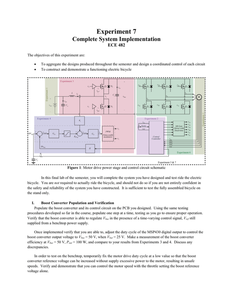
Experiment 7 Complete System Implementation ECE 482 The objectives of this experiment are: To aggregate the designs produced throughout the semester and design a coordinated control of each circuit To construct and demonstrate a functioning electric bicycle Figure 1: Motor drive power stage and control circuit schematic In this final lab of the semester, you will complete the system you have designed and test ride the electric bicycle. You are not required to actually ride the bicycle, and should not do so if you are not entirely confident in the safety and reliability of the system you have constructed. It is sufficient to test the fully assembled bicycle on the stand only. I. Boost Converter Population and Verification Populate the boost converter and its control circuit on the PCB you designed. Using the same testing procedures developed so far in the course, populate one step at a time, testing as you go to ensure proper operation. Verify that the boost converter is able to regulate Vbus in the presence of a time-varying control signal, Vref still supplied from a benchtop power supply. Once implemented verify that you are able to, adjust the duty cycle of the MSP430 digital output to control the boost converter output voltage to Vbus = 50 V, when Vbat = 25 V. Make a measurement of the boost converter efficiency at Vbus = 50 V, Pout = 100 W, and compare to your results from Experiments 3 and 4. Discuss any discrepancies. In order to test on the benchtop, temporarily fix the motor drive duty cycle at a low value so that the boost converter reference voltage can be increased without supply excessive power to the motor, resulting in unsafe speeds. Verify and demonstrate that you can control the motor speed with the throttle setting the boost reference voltage alone. II. E-Bike Testing Test your complete system indoors. In the final week of class, bicycles with batteries will be available. Connect, through the required protection, your circuit to the motor and battery. Verify that the motor spins with speed controlled by the throttle, and can be successfully started, brought to speed, and can coast down without issue. You may use the mechanical brake as necessary to slow the system down. If you are confident in the system and would like to, you may test the e-bike off the stand, outdoors, with instructor present. Note that all Tennessee state bicycle safety laws still apply, including a speed limit of 20 mph for e-bikes on public streets. You are not required, and will not be penalized, if you choose not to complete this step. For full credit, you must only operate the complete system (with motor and battery) on the stand in the lab. III. Deliverables The deliverables for the final project of the semester are (1) demo of a functioning, complete system on or before April 23rd and (2) a technical reference manual for your completed electric bicycle. The report should include the following: General Overview: highlighting the purpose and key features of the system System Description: block diagrams & (brief) description of functionality and use of your implementation, capabilities and operating ranges Implementation Details: block diagrams and descriptions of their internal operation, including justification of why a system was designed as-is Verification: simulations, and experimental results demonstrating the achieved operation of each block and the overall system Conclusions: including future steps, as you see them, to improve system performance and any comments on your system's successes, failures, or things you would do differently Additionally, the following should be included as Appendices as well as additional supplemental files to the report: Schematics PCB Layout Parts List MSP430 Codes The technical reference manual and associated files should be sufficient to allow anyone with an appropriate background to reconstruct an exact copy of your system. The depth and comprehensiveness of the reference manual should be comparable to the datasheets and user guides/manuals used in this course.
