AN-722 APPLICATION NOTE
advertisement
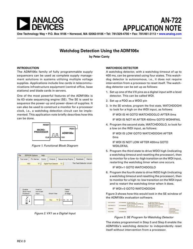
AN-722 APPLICATION NOTE One Technology Way • P.O. Box 9106 • Norwood, MA 02062-9106 • Tel: 781/329-4700 • Fax: 781/461-3113 • www.analog.com Watchdog Detection Using the ADM106x by Peter Canty INTRODUCTION The ADM106x family of fully programmable supply sequencers can be used as complete supply management solutions in systems utilizing multiple voltage supplies. Applications include line cards in telecommunications infrastructure equipment (central office, base stations) and blade cards in servers. One of the most powerful features of the ADM106x is its 63-state sequencing engine (SE). The SE is used to sequence the power-up and power-down of supplies. It can also be used to construct a monitor for a processor clock, i.e., a watchdog detection circuit can be implemented. This application note briefly describes how this can be done. RESET MICROPROCESSOR CLK PDO1 ADM106x VX1 Figure 1. Functional Block Diagram WATCHDOG DETECTOR A watchdog detector, with a watchdog timeout of up to 400 ms, can be generated using four states. This watchdog detector is autonomous, i.e., it does not require intervention from a processor to reset itself. The watchdog detector can be set up as follows: 1. Set up one of the VX pins as a digital input with a level detector. This can be called WDI. 2. Set up a PDO as a WDO pin 3. In the SE window, program the first state, WATCHDOGHI to look for a high on the WDI input, as follows: IF WDI IS HI GOTO WATCHDOGLO AFTER 0ms IF WDI IS NOT HI AFTER 400ms GOTO WDIHIFAIL 4. Program the second state, WATCHDOGLO, to look for a low on the WDI input, as follows: IF WDI IS LOW GOTO WATCHDOGHI AFTER 0ms IF WDI IS NOT LOW AFTER 400ms GOTO WDILOFAIL 5. Program the third state to drive WDO high (indicating a watchdog timeout and resetting the processor), then to monitor for a low-to-high transition on the WDI input, restarting the watchdog timer when one occurs. IF WDI=1 GOTO WATCHDOGLO 6. Program the fourth state to drive WDO high (indicating a watchdog timeout and resetting the processor), then to monitor for a high-to-low transition on the WDI input and to restart the watchdog timer when it does. IF WDI=0 GOTO WATCHDOGHI Figure 3 shows how this would look in the SE window of the ADM106x evaluation software. Figure 2. VX1 as a Digital Input Figure 3. SE Program for Watchdog Detector The states programmed in Step 5 and Step 6 enable the ADM106x’s watchdog detector to independently reset itself without intervention from a processor. REV. 0 AN-722 AN04840–0–2/06(0) WATCHDOG DETECTOR WITH TIMEOUT GREATER THAN 400 ms 400 ms may not be a long enough timeout for some processor clocks. For instance, 1.6 seconds is a popular timeout for many watchdog detector circuits. Longer timeouts can be achieved with the ADM106x using extra states. For a 1.6 s timeout, four states, each with a maximum timeout of 400 ms, are required. The coding for the four states is very similar. Figure 4 shows the code as it would appear in the ADM106x application software. Figure 4. 1.6 Second Timeout Watchdog Detector © 2006 Analog Devices, Inc. All rights reserved. Trademarks and registered trademarks are the property of their respective owners. –2– REV. 0


