Tech Tips Aviation Management National Technology &
advertisement

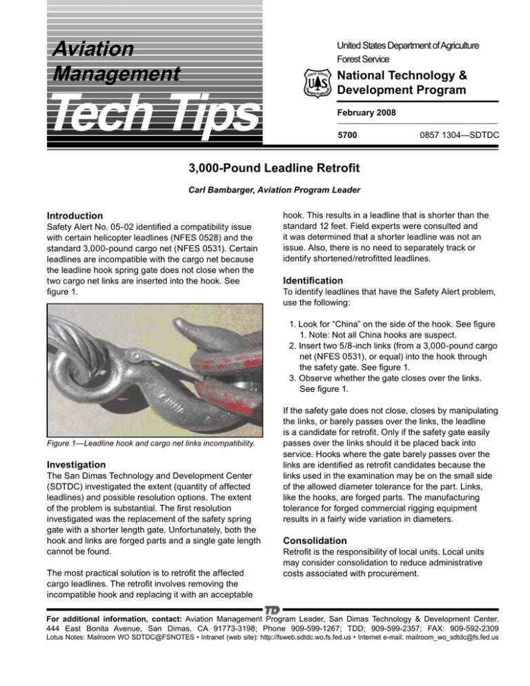
Aviation Management United States Department of Agriculture Forest Service Tech Tips National Technology & Development Program February 2008 5700 0857 1304—SDTDC 3,000-Pound Leadline Retrofit Carl Bambarger, Aviation Program Leader Introduction Safety Alert No. 05-02 identified a compatibility issue with certain helicopter leadlines (NFES 0528) and the standard 3,000-pound cargo net (NFES 0531). Certain leadlines are incompatible with the cargo net because the leadline hook spring gate does not close when the two cargo net links are inserted into the hook. See figure 1. hook. This results in a leadline that is shorter than the standard 12 feet. Field experts were consulted and it was determined that a shorter leadline was not an issue. Also, there is no need to separately track or identify shortened/retrofitted leadlines. Identification To identify leadlines that have the Safety Alert problem, use the following: 1. Look for “China” on the side of the hook. See figure 1. Note: Not all China hooks are suspect. 2. Insert two 5/8-inch links (from a 3,000-pound cargo net (NFES 0531), or equal) into the hook through the safety gate. See figure 1. 3. Observe whether the gate closes over the links. See figure 1. Figure 1—Leadline hook and cargo net links incompatibility. Investigation The San Dimas Technology and Development Center (SDTDC) investigated the extent (quantity of affected leadlines) and possible resolution options. The extent of the problem is substantial. The first resolution investigated was the replacement of the safety spring gate with a shorter length gate. Unfortunately, both the hook and links are forged parts and a single gate length cannot be found. The most practical solution is to retrofit the affected cargo leadlines. The retrofit involves removing the incompatible hook and replacing it with an acceptable If the safety gate does not close, closes by manipulating the links, or barely passes over the links, the leadline is a candidate for retrofit. Only if the safety gate easily passes over the links should it be placed back into service. Hooks where the gate barely passes over the links are identified as retrofit candidates because the links used in the examination may be on the small side of the allowed diameter tolerance for the part. Links, like the hooks, are forged parts. The manufacturing tolerance for forged commercial rigging equipment results in a fairly wide variation in diameters. Consolidation Retrofit is the responsibility of local units. Local units may consider consolidation to reduce administrative costs associated with procurement. For additional information, contact: Aviation Management Program Leader, San Dimas Technology & Development Center, 444 East Bonita Avenue, San Dimas, CA 91773-3198; Phone 909-599-1267; TDD; 909-599-2357; FAX: 909-592-2309 Lotus Notes: Mailroom WO SDTDC@FSNOTES • Intranet (web site): http://fsweb.sdtdc.wo.fs.fed.us • Internet e-mail: mailroom_wo_sdtdc@fs.fed.us Retrofit Requirements Appendix A is the Statement of Work and should be used to establish minimum retrofit requirements. The retrofit is considered a common commercial action, and therefore should not require specialized knowledge among the field units. Local commercial or industrial rigging companies should be qualified to meet the requirements of the retrofit program. Retrofit is the alternative to scrapping current inventory and procuring new leadlines. Retrofit should be completed only if savings are attainable. SDTDC obtained an approximate 40-percent savings over replacement in the “proof-ofconcept” process. This percentage is not a benchmark, but merely SDTDC’s experience. Local units must make their own determination and justify their choice. SDTDC is aware of one retrofit program where savings were in excess of 40 percent, based on a larger quantity of retrofitted leadlines. If the original identification tag is still attached to the leadline, leave it attached. In addition to appendix A, give the vendor a copy of this Tech Tip. It will help him/her understand the inspection/ acceptance requirements. Field Inspection and Acceptance Field personnel should inspect the returned product for quality and assure that the contract requirements are met. Field personnel must inspect the lot for the elements shown in table 1. Inspection and acceptance of the returned product should be based on the following: Table 1. Major criteria inspection table. Method of Inspection Measure Examination Appendix A Reference Paragraph Measure the hook to assure the dimensions are met. Review the contractor’s submitted Certificate of Conformance for the ultimate load capacity of the hook. Measure the gate release lock engagement to assure the dimension is as required. Typically this can be done by measuring the bare metal area of the gate lock. 1.b Visual Assure that the hook is coated for corrosion, e.g., painted, plated, etc. 1.d Review Review the contractor’s submitted Certificate of Conformance for the rating of the thimbles as heavy duty or extra heavy. 2 Visual Assure that the marking tag contains all of the required information. 3 Measure Measure the character heights to assure they are as required. Assure that the characters are legible and permanently stamped, embossed, cut, or etched on the metal tag. Assure the tag is made of stainless or brass. Assure the tag is oriented in the swage properly, a steel cable is used to hold the tag and the loop is as required. Review the submitted documentation to assure the finished assembly was proof tested to 6,000 pounds. 3 Measure the cable to assure that it is not less than 10 feet 2 inches. 6 Visual Assure that the swage collar is copper or zinc-coated copper. 8 Visual Assure that the swage collar has been painted for slip indication. 8 Visual Assure that no plastic coating was included in the swage. 8 Review Measure Visual Visual Visual Review Measure 2 1.a 1.c 3 3 3 4 Do not inspect every part. Use table 2 to determine sample size and reject criteria. Count the number of parts in the lot, and based on that quantity determine the sample size. Then select a random sample of parts from the delivered lot. Each leadline from the sample is examined for the criteria in table 1. Count the total number of defects found that violate of the requirements identified in table 1. (Note: The same defect found on two different leadlines of the sample is considered two defects, not one defect.) Upon completing the inspection, reject the lot if the quantity of accumulated defects exceeds the number shown in table 2 for the sample size. The vendor may resubmit a rejected lot after defects have been eliminated. Field personnel shall use the same inspection process for the resubmitted lot. Table 2—Sample size and reject criteria. Number of parts (quantity up to) Sample size 8 15 25 50 90 150 280 500 1,200 3,200 2 2 3 5 5 8 13 20 32 50 Reject all parts after finding more than this many defects in the sample size 0 0 0 0 0 0 1 1 1 2 Example: The quantity of retrofitted leadlines is 65. According to table 2, the sample size for inspection should be 5; 65 is greater than 50, but less than 90. From the total lot of leadlines (65) take a random sample of 5 leadlines. Inspect the parts for the parameters shown in table 1, counting the number of defects. After inspecting all of the leadlines from the sample, if the total number of defects is greater than 0, then the entire lot of leadlines is not accepted and the vendor must rework or replace them for no additional cost. 3 Appendix A Leadline Retrofit Statement of Work Purpose: These instructions are provided in response to Safety Alert No. 05-02. The government has in its inventory many leadlines whose hooks are too small for use. As such, the government is interested in the retrofit of these items. This Statement of Work defines the requirements for this retrofit. The contractor shall retrofit the supplied government leadlines to the following requirements: 1. The contractor shall remove the existing hook and replace it with a hook that meets the following: a. The hook shall have a minimum ultimate load of 11,250 pounds. b. The hook shall have the dimensions shown in figure A1. Figure A1—Hooks. c. A gate release shall be incorporated in the hook and have a spring return to lock the gate closed. The release lock and hook gate shall have a minimum engagement of 0.130 inches, as shown in figure A2, gate lock engagement. (Note: The dashed lines in figure A2 are hidden lines.) Figure A2—Gate lock engagement. d. The hook shall be treated for corrosion resistance. e. The contractor shall provide a Certificate of Conformance (COC) in accordance with paragraph 5 for the hook. 2. The contractor may reuse the thimble from the removed hook end if it is in serviceable condition. The contractor may supply a new thimble if the original one is damaged or not usable. The new thimble shall be rated extra heavy or heavy duty; and shall be galvanized coated. If a replacement thimble is used, the contractor shall supply a COC for the thimble. 5 3. The contractor shall mark each retrofit leadline item with a tag showing the information in figure A3. (Note: The date and company shown below in the tag information is a sample. The actual date (month and year) of manufacture and proof testing shall be used.) The text height shall be 0.12 inches minimum. The text shall be legibly and permanently stamped, embossed, cut, or etched on to metal tag. The tag shall be either stainless steel or brass. The tag shall be attached to the leadline at the hook-end using a 1/16-inch galvanized steel wire rope. The hole in the tag shall be greater than 1-½-hole diameters away from any edge of the tag. This tag wire rope shall be included in the swaging which attaches the hook. The loop formed shall be between 1 and 1-½ inches in diameter and oriented in the swage in the direction shown in figure A4. a. Item description, i.e., eyelet hook, thimble. b. Item manufacturer’s name, address, and telephone number. c. Manufacturer’s item part number. d. Procuring document for the item (to include the quantity and date ordered). e. Manufacturer’s lot number, if applicable. f. Manufacturer’s statement of safe working load and ultimate strength for the item, or part rating (applicable to thimbles only). 6. When removing the original hook from the leadline, the contractor shall ensure that the maximum length of the new leadline is achieved. The length of the leadline shall be measured from the inner load surface of each thimble while the leadline is laid out flat in a straight line. See figure A5. The minimum length shall be 10 feet 2 inches for the retrofitted assembly. Figure A3—Tag information. Figure A5—Note the ring and hook are removed for clarity. 7. The retrofit leadline shall be manufactured by current standard production processes to provide a clean, finished quality product. Workmanship shall be equal to the best commercial practices consistent with the highest engineering standards in the industry and shall be free from any defect that may impair serviceability or detract from the appearance of the product. The leadline shall be free of sharp edges or other that could result in injury. Figure A4—Tag orientation in swage. 4. Each and every leadline shall be proof-tested to 6,000 pounds before delivery to the government. The contractor shall provide evidence for each applied proof test. The test equipment shall be calibrated to a recognized State or Federal standard. Calibration of the test equipment shall have occurred within the last 12 months of the proof-testing. The applied load shall be a static load and held for a minimum of 10 seconds. 8. The new hook shall be terminated in an eye using a thimble and a copper or zinc coated copper swage sleeve/collar. Aluminum swages/collars shall not be used. The wire rope shall be stripped of the plastic coating before swaging. The swaged area shall not incorporate any part of the plastic coating. All swages shall be painted for slip indication (see figure A6). The paint color shall be red. The paint shall be applied by spraying and applied in the area shown in figure A6 all around the outside of the leadline. Swages shall not be covered. No splices shall be allowed in the cable. The terminated hook end of the cable shall be fully contained within their 5. The contractor shall provide individual COCs for the component where required in this specification. The contractor shall provide the following information on the certificate: 6 swages, i.e., the end of the wire rope shall be flush with the swage collar or extend outside the collar no more than 0.125 inches. In no case shall the end of the cable be contained within the collar, i.e., recessed inside the collar after swaging. Painted area red Figure A6—Slip indicator paint. Note to Vendors. The leadlines were procured to a specification that established the minimum tensile strength of the raw wire rope material at a minimum of 11,250 pounds. Certifications were obtained at the time of procurement validating this. Hence, leadlines shall not be rejected due to doubts about the strength of the wire rope material. Leadlines may be rejected do to unacceptable wear or damage to the wire rope. End of Statement of Work. 7 The information contained in this publication has been developed for the guidance of employees of the U.S. Department of Agriculture (USDA) Forest Service, its contractors, and cooperating Federal and State agencies. The USDA Forest Service assumes no responsibility for the interpretation or use of this information by other than its own employees. The use of trade, firm, or corporation names is for the information and convenience of the reader. Such use does not constitute an official evaluation, conclusion, recommendation, endorsement, or approval of any product or service to the exclusion of others that may be suitable. The U.S. Department of Agriculture (USDA) prohibits discrimination in all its programs and activities on the basis of race, color, national origin, age, disability, and where applicable, sex, marital status, familial status, parental status, religion, sexual orientation, genetic information, political beliefs, reprisal, or because all or part of an individual’s income is derived from any public assistance program. (Not all prohibited bases apply to all programs.) Persons with disabilities who require alternative means for communication of program information (Braille, large print, audiotape, etc.) should contact USDA’s TARGET Center at (202) 720-2600 (voice and TDD). To file a complaint of discrimination, write USDA, Director, Office of Civil Rights, 1400 Independence Avenue, S.W., Washington, D.C. 20250-9410, or call (800) 795-3272 (voice) or (202) 720-6382 (TDD). USDA is an equal opportunity provider and employer.


