3D LANDMARKS – GENERATION, CHARACTERISTICS AND APPLICATIONS
advertisement
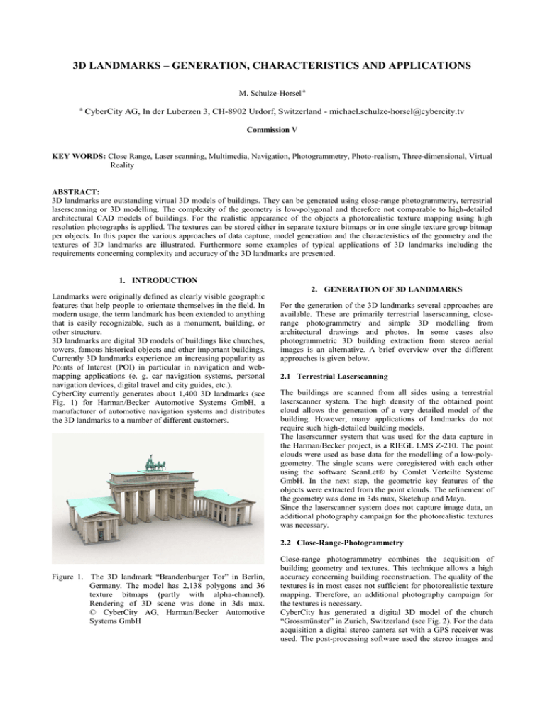
3D LANDMARKS – GENERATION, CHARACTERISTICS AND APPLICATIONS M. Schulze-Horsel a a CyberCity AG, In der Luberzen 3, CH-8902 Urdorf, Switzerland - michael.schulze-horsel@cybercity.tv Commission V KEY WORDS: Close Range, Laser scanning, Multimedia, Navigation, Photogrammetry, Photo-realism, Three-dimensional, Virtual Reality ABSTRACT: 3D landmarks are outstanding virtual 3D models of buildings. They can be generated using close-range photogrammetry, terrestrial laserscanning or 3D modelling. The complexity of the geometry is low-polygonal and therefore not comparable to high-detailed architectural CAD models of buildings. For the realistic appearance of the objects a photorealistic texture mapping using high resolution photographs is applied. The textures can be stored either in separate texture bitmaps or in one single texture group bitmap per objects. In this paper the various approaches of data capture, model generation and the characteristics of the geometry and the textures of 3D landmarks are illustrated. Furthermore some examples of typical applications of 3D landmarks including the requirements concerning complexity and accuracy of the 3D landmarks are presented. 1. INTRODUCTION 2. GENERATION OF 3D LANDMARKS Landmarks were originally defined as clearly visible geographic features that help people to orientate themselves in the field. In modern usage, the term landmark has been extended to anything that is easily recognizable, such as a monument, building, or other structure. 3D landmarks are digital 3D models of buildings like churches, towers, famous historical objects and other important buildings. Currently 3D landmarks experience an increasing popularity as Points of Interest (POI) in particular in navigation and webmapping applications (e. g. car navigation systems, personal navigation devices, digital travel and city guides, etc.). CyberCity currently generates about 1,400 3D landmarks (see Fig. 1) for Harman/Becker Automotive Systems GmbH, a manufacturer of automotive navigation systems and distributes the 3D landmarks to a number of different customers. For the generation of the 3D landmarks several approaches are available. These are primarily terrestrial laserscanning, closerange photogrammetry and simple 3D modelling from architectural drawings and photos. In some cases also photogrammetric 3D building extraction from stereo aerial images is an alternative. A brief overview over the different approaches is given below. 2.1 Terrestrial Laserscanning The buildings are scanned from all sides using a terrestrial laserscanner system. The high density of the obtained point cloud allows the generation of a very detailed model of the building. However, many applications of landmarks do not require such high-detailed building models. The laserscanner system that was used for the data capture in the Harman/Becker project, is a RIEGL LMS Z-210. The point clouds were used as base data for the modelling of a low-polygeometry. The single scans were coregistered with each other using the software ScanLet® by Comlet Verteilte Systeme GmbH. In the next step, the geometric key features of the objects were extracted from the point clouds. The refinement of the geometry was done in 3ds max, Sketchup and Maya. Since the laserscanner system does not capture image data, an additional photography campaign for the photorealistic textures was necessary. 2.2 Close-Range-Photogrammetry Figure 1. The 3D landmark “Brandenburger Tor” in Berlin, Germany. The model has 2,138 polygons and 36 texture bitmaps (partly with alpha-channel). Rendering of 3D scene was done in 3ds max. © CyberCity AG, Harman/Becker Automotive Systems GmbH Close-range photogrammetry combines the acquisition of building geometry and textures. This technique allows a high accuracy concerning building reconstruction. The quality of the textures is in most cases not sufficient for photorealistic texture mapping. Therefore, an additional photography campaign for the textures is necessary. CyberCity has generated a digital 3D model of the church “Grossmünster” in Zurich, Switzerland (see Fig. 2). For the data acquisition a digital stereo camera set with a GPS receiver was used. The post-processing software used the stereo images and the GPS coordinates of the image capture positions for the generation of a 3D point cloud with edge points of the building. Using an export interface this point cloud was exported to AutoCAD. Here the modelling of lines and faces was carried out. Figure 2. 3D landmark of the church “Grossmünster” in Zurich, Switzerland. The model has 2,000 polygons and 82 texture bitmaps (partly with alpha-channel). Rendering of 3D scene was done in 3ds max. © CyberCity AG 2.3 3D Modelling Simple 3D modelling represents the third approach of creating 3D landmarks. Experienced 3D modellers use architectural drawings, photos and in some cases distance measurements from a laser range finder in order to create a 3D landmark. A number of 3D software solutions is available for the costefficient 3D modelling and texture mapping. This can be professional software like 3ds max and Maya from Autodesk, but also freeware like Google Sketchup or open-source products like Wings3D. In most cases, objects derived from laserscanning and photogrammetry require an additional optimization of the geometry. The complexity of the geometry like number of polygons or triangles has to be adjusted to the given specifications. The advantage of manual 3D modelling is that the complexity of the geometry can be adjusted by the 3D artist during the modelling process. No automatic polygon reduction algorithms are necessary that might cause unwanted changes in the geometry. The geometric accuracy is lower compared to laserscanning and close-range photogrammetry. However, the significant lower price for the production justifies this approach. The geometry of a 3D landmark is not comparable to highpolygonal 3D building models (“high-poly models”). Those are mostly built of hundreds of thousands of polygons whereas 3D landmarks have a very simple geometry. The number of polygons ranges from some hundreds to 1,500 – 2,000, in rare cases up to 4,000. 2.4 3D building extraction using stereo aerial images If high resolution stereo aerial images are available, the buildings are generated using a photogrammetric semiautomatic 3D building extraction procedure developed by CyberCity. This approach is useful for both area-wide 3D city models and single 3D landmark objects (see Fig. 3). The advantage compared to 3D modelling from photos is that the geometric accuracy of the buildings is very high but the complexity is low as no detailed structures of the buildings (as it is the case for 3D landmarks from LIDAR data) are modelled. Furthermore, each building is located at its correct geographic position and elevation. This information can be used for the creation of an external coordinate file. Figure 3. The Fortress Hohensalzburg in Salzburg, Austria. The building is part of a area-wide 3D city model which was generated by CyberCity. The geometry has been extracted from stereo aerial images using photogrammetry. Roof and facades have been textured semi-automatically using oblique aerial images. © CyberCity AG, ViewTec AG, Forest Mapping Management GmbH 2.5 Texturing In order to make the 3D landmarks look photorealistic, a texture mapping has to be done after the modelling. High resolution digital photographs are used for the texturing. Unlike photos which are acquired for photogrammetry, texture images must always be acquired as perpendicular as possible to the facade of the building to ensure a high texture quality and to reduce the work for texture editing. Also the exposure settings of the camera should be always the same in order to reduce colour corrections. Before being used as textures, the images are rectified and cleaned from disturbing objects like trees. The texture mapping workflow in Maya has been improved by some scripts which help the 3D artists for example to remove redundant mappings, change and extend the mapping to other faces, etc. In general, those scripts make the texture mapping workflow easier to perform for unexperienced operators. As the wire frame geometry of the 3D landmarks is rather simple, a good texture quality is required in order to simulate a more complex geometry (see Fig. 4). Alternatively, the software CyberCity-Modeler provides various texture mapping procedures. A very efficient approach for photorealistic texture mapping is the semi-automatic processing of oblique aerial images. Fence-like structures, for example, are modelled using only a few faces. but are textured using a texture with an alpha-channel which controls the transparency of the textures. Two different ways of texturing are applied for the texture mapping: 1. Each face or a group of faces is textured using a separate texture bitmap. This provides higher flexibility concerning the use of different materials and the modification of single texture bitmaps. 2. All textures are stored as a group in one single bitmap per model. This increases the speed for loading significantly. Texture groups have generally the dimensions of 2n pixels (e.g. 128x64, 512x512,…). Textures with dimensions of 2n can be handled faster by 3D visualization systems. Further texture optimization includes also editing of the UV coordinates in order to use texture memory as efficiently as possible, i. e. repeated texture elements. 3. CHARACTERISTICS In most 3D file formats the wire frame geometry and the texture bitmaps are stored separately. Some of the most frequently used file formats are .3DS (3D Studio), .MAX (3ds max), .MB and .OBJ (both Maya), .FLT (MultiGen) and .WRL. The advantage of separate texture bitmaps is that the textures can be modified or replaced by another bitmap. If the data format is ASCIIbased (e.g. VRML), texture links in the file can be modified easily using a standard text editor. Unlike all data in Geographic Information Systems the 3D landmarks always have a local coordinate system. The reason for this is that most 3D software solutions – both 3D modelling software and 3D visualization software – are not able to compute accurate vertex positions for large coordinate values (e.g. X=3465000, Y=5549000) from geographic coordinate systems. As a consequence of that, objects are not displayed properly (see Fig. 5). If 3D landmarks are used for 3D map applications which have a geographic coordinate system, the centre of the 3D object is referenced to an anchor point on the map using an external file with the coordinate information. Figure 5. Screenshots from Autodesk 3ds max. Left: 3D object with errors in the geometry. Large coordinate values cause errors in the vertex positions. Right: Small coordinate values with the origin of the coordinate system in the centre of the 3D object. No errors in the vertex positions occur. Figure 4. 3D landmark of the Historic City Hall in Sindelfingen, Germany. Top: Geometry model with outlines of faces. Centre: Geometry model with shaded faces. Bottom: Geometry model with photorealistic textures. The 3D landmark has 229 polygons and 42 texture bitmaps. © Harman/Becker Automotive Systems GmbH When 3D landmarks are generated, the structure of the underlying terrain plays an important role for the modelling of the object. In many cases the terrain beneath the buildings is not flat (see Fig. 6). CyberCity has generated 3D models buildings and historical monuments in Vienna by order of the City of Vienna (see Fig. 7). The objects have been scanned with a terrestrial laserscanner. Additionally, photographs for photorealistic texture mapping were captured. 4.2 Architecture visualization 3D landmarks are also used for architecture visualizations. These applications require a high quality of the 3D objects. The number of polygons and the resolution of the textures are higher than for navigation applications (see below). For visualization of the architectural concept, the landscape architects “von Canal architekten und ingenieure” in Koblenz, Germany used photo-realistic 3D Landmarks and won the award of the competition for the National Garden Show (BUGA) 2011 in Koblenz, Germany (see Fig. 8). Figure 6. 3D landmark of the church “Grossmünster” in Zurich, Switzerland. The slope of the underlying terrain is clearly visible in the 3D object. No adjustment has been performed yet. © CyberCity AG Depending on whether the 3D landmark is placed geographically correctly in a larger context with other objects or regarded as a single object, the basement of the building has to be adjusted. This can be done, for example, by combining the building object with a Digital Terrain Model (DTM). Geometry and textures of the object are fitted seamlessly to the DTM. Alternatively a geometric element with neutral colours can be added to the building in order to flatten the basement. 4. APPLICATIONS OF 3D LANDMARKS 3D landmarks are used for a number of visualization applications. Potential customers have different requirements concerning complexity, accuracy and price of 3D landmarks. Figure 8. Award-winning landscape-architectural concept for the National Garden Show 2011 in Koblenz, Germany. © CyberCity AG, von Canal architekten und ingenieure. 4.3 Real estate management, location marketing The company Infraserv GmbH & Co. Höchst KG, operator of the industrial park Höchst in Frankfurt, Germany, has mandated CyberCity to create a virtual 3D model of the industrial site. About 800 building groups are located in the area. 4.1 Urban planning, local government If municipalities use area-wide 3D city models for urban planning and city marketing applications, they can populate the 3D city models with the comparatively high detailed 3D landmarks. Figure 7. 3D landmark of the District Heating Plant Spittelau in Vienna, Austria. The object is built of 3,814 polygons and 185 textures (partly with alphachannel). Figure 9. Untextured model of a planned power plant in the industrial park of Höchst, Frankfurt, Germany. The start of construction is scheduled for the first half of 2007. © Infraserv GmbH & Co. Höchst KG Infraserv uses the virtual 3D model for the acquisition of new customers willing to settle down in the industrial park. Besides existing buildings, also planned buildings like a power plant (see Fig. 9) can be integrated in the 3D model. As for architectural visualization applications, the complexity of the model should be higher than for navigation applications. 4.4 Web based visualization solutions, Tourism Web based visualization solutions like Google Earth, TerrainView Web and Map2Day are globally accessible platforms to visualize not only 3D landmarks but also area-wide 3D city models (see Fig. 10). Due to performance reasons it is crucial to introduce several Levels of Detail (LOD) of both geometry and textures. Web based 3D visualization solutions are also used for tourism applications. Tourists can explore their holiday destinations via Internet to plan their vacations. all 3D games that play in the present and in the real world – flight simulators in particular – can use 3D landmarks and 3D city models. The entertainment industry’s requirements are different than the architecture’s. High geometric accuracy is not required; most important is a good over-all appearance of the object. Important requirements for 3D simulators are the texture groups with an extension of 2n pixels. Due to a strong competition and a high cost pressure the price for this service is comparatively low. As a consequence of this the data capture using laserscanning and photogrammetry is not competitive for game projects. 4.7 3D simulators (flight simulators, driving simulators, etc.) For professional 3D simulation systems (e.g. flight simulators, driving simulators, train simulators, etc.) detailed and photorealistic 3D city models and 3D landmarks are required. 5. CONCLUSIONS Figure 10. Screenshot from Map2Day with TerrainView Web™, a 3D realtime visualization plugin for webbrowsers. The 3D scene shows a part of the photorealistic 3D city model of Salzburg, Austria, which was created by CyberCity. © CyberCity AG, ViewTec AG, Forest Mapping Management GmbH 4.5 Navigation systems The market for navigation devices, digital city guides, and route planners is growing rapidly. We differentiate between the fixed automotive navigation systems and the mobile personal navigation devices. With the hardware becoming continuously more powerful, Harman/Becker has introduced 3D landmarks as a new feature for the coming generation of premium class automotive navigation systems. These systems have a 3D graphics chip and can therefore display 3D geometries. The systems display a rather simple 3D city model as “background” with selected buildings as photorealistic 3D landmarks. The development towards the third dimension will spread this new feature into the mass market of mobile navigation devices, too. However, the market currently demands 3D landmarks with a significantly lower complexity than the Harman/Becker landmarks have. 4.6 Entertainment (TV, movies, games) Landmarks are also used for applications in the entertainment industry. They are used not only for the production of TV programs and movies but also for computer games. In principal, Several technologies of data capture and 3D landmark generation are currently available. It could be shown that different applications require various specifications in terms of accuracy and complexity of the 3D landmarks. This causes different price schemes in the markets. Whereas data capture using terrestrial laserscanning and closerange photogrammetry is rather suitable for applications where a high geometric accuracy is required (e. g. architecture visualization), in the entertainment industry and in particular in the game market, the cost-efficiency of the data production has a much higher priority than geometric accuracy. Provided that appropriate source data, i. e. stereo aerial images and oblique aerial images, is available, the CyberCity technology of photogrammetric 3D building extraction in combination with texture-mapping represents a cost-efficient alternative for the production of photorealistic and accurate 3D landmarks. 6. ACKNOWLEDGEMENTS The author would like to thank Dr. Xinhua Wang and Robert Bosch from CyberCity AG as well as Volker Grabs from Harman/Becker Automotive Systems GmbH for their assistance when writing this article.
