The INTERFEROMETRIC RECONSTRUCTION USE of
advertisement
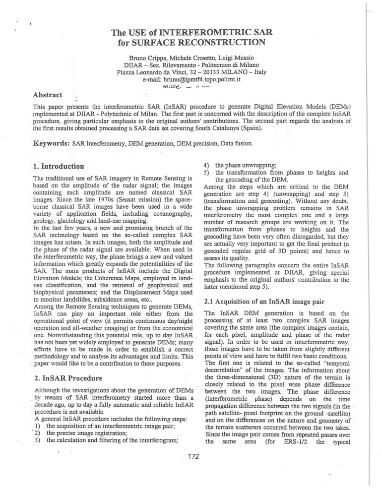
The USE of INTERFEROMETRIC SAR
for SURFACE RECONSTRUCTION
Bruno Crippa, Michele Crosetto, Luigi Mussio
DIIAR- Sez. Rilevamento - Politecnico di Milano
Piazza Leonardo da Vinci, 32-20133 MILANO - Italy
e-mail: bruno@ipmtf4.topo.polimi.it
W\ ·~-
•l -
Abstract
This paper presents the interferometric SAR (InSAR) procedure to generate Digital Elevation Models (DEMs)
implemented at DIIAR - Polytechnic of Milan. The first part is concerned with the description of the complete InSAR
procedure, giving particular emphasis to the original authors' contributions. The second part regards the analysis of
the first results obtained processing a SAR data set covering South Catalunya (Spain).
Keywords: SAR Interferometry, DEM generation, DEM precision, Data fusion.
the phase unwrapping;
5) the transformation from phases to heights and
the geocoding of the DEM.
Among the steps which are critical to the DEM
generation are step 4) (unwrapping) and step 5)
(transformation and geocoding). Without any doubt,
the phase unwrapping problem remains in SAR
interferometry the most complex one and a large
number of research groups are working on it. The
transformation from phases to heights and the
geocoding have been very often disregarded, but they
are actually very important to get the final product (a
geocoded regular grid of 3D points) and hence to
assess its quality.
The following paragraphs concern the entire InSAR
procedure implemented at DIIAR, giving special
emphasis to the original authors' contribution to the
latter mentioned step 5).
4)
1. introduction
The traditional use of SAR imagery in Remote Sensing is
based on the amplitude of the radar signal; the images
·containing such amplitude are named classical SAR
images. Since the late 1970s (Seasat mission) the spaceborne classical SAR images have been used in a wide
variety of application fields, including oceanography,
. geology, glaciology and land-use mapping.
In the last few years, a new and promising branch of the
SAR technology based on the so-called complex SAR
images has arisen. In such images, both the amplitude and
the phase of the radar signal are available. When used in
the Interferometric way, the phase brings a new and valued
information which greatly expands the potentialities of the
SAR. The main products of InSAR include the Digital
Elevation Models; the Coherence Maps, employed in landuse classification, and the retrieval of geophysical and
biophysical parameters; and the Displacement Maps used
to monitor landslides, subsidence areas, etc ..
2.1 Acquisition of an InSAR image pair
Among the Remote Sensing techniques to generate DEMs,
The InSAR DEM generation is based on the
InSAR can play an important role either from the
processing of at least two complex SAR images
operational point of view (it permits continuous day/night
covering the same area (the complex images contain,
operation and all-weather imaging) or from the economical
·one. Notwithstanding this potential role, up to day InSAR . for each pixel, amplitude and phase of the radar
signal). In order to be used in interferometric way,
has not been yet widely employed to generate DEMs; many
those images have to be taken from slightly different
efforts have to be made in order to establish a correct
points of view and have to fulfil two basic conditions.
methodology and to analyse its advantages and limits. This
The first one is related to the so-called "temporal
. paper would like to be a contribution to these purposes.
decorrelation" of the images. The information about
the three-dimensional (3D) nature of the terrain is
2. InSAR Procedure
closely related to the pixel wise phase difference
Although the investigations about the generation of DEMs
between the two images. The phase difference
by means of SAR interferometry started more than a
(interferometric phase) depends on the time
decade ago, up to day a fully automatic and reliable InSAR
propagation difference between the two signals (in the
· procedure is not available.
path satellite- pixel footprint on the ground -satellite)
A general InSAR procedure includes the following steps:
and on the differences on the nature and geometry of
1) the acquisition of an interferometric image pair;
the terrain scatterers occurred between the two takes.
· 2) the precise image registration;
Since the image pair comes from repeated passes over
3) the calculation and filtering of the interferogram;
the same area (for ERS-1/2 the typical
172
Figure 1: Interferometric phase before and after filtering with the ISAR software.
pass intervals are 1,3,35 and 176 days), and since the
useful interferometric information is only related to
the time-propagation difference between the two
signals, it is very important the physical terrain
characteristics do not undergo sensible changes
between the different passes.
In case these changes occur (e.g. due to rain, snow or
vegetation growth), they originate the "temporal
decorrelation" which, depending on its magnitude,
can even make the interferometric phase useless for
the DEM generation. The second condition to be
fulfilled concerns the "geometric decorrelation". The
simple fact that the images are taken from not exactly
the same point of view engenders a loss of correlation
(also called coherence) between the two images and
hence noise in the interferometric phase. The image
coherence loss is proportional to the satellite baseline
length; the "critical baseline" is the value of the base
length to which corresponds zero coherence. For
ERS-1/2 this value is approximately equal to 1 km,
but usually with baselines longer than 500 m there is
no more interferometric information because other
noise sources sum up to the geometric decorrelation.
This limit on the baseline has to be considered in the
image pair choice.
footprint on the ground. This condition is not fulfilled
by the original images because they only
approximately cover the same area and they have
been acquired from different points of view and from
not exactly parallel orbits.
To ·perform the registration, the transformation from
one image geometry to another must be found, and
the resampling of one of the two images must be
performed. This operation has to be very precise
(realised with sub-pixel accuracy) in order to preserve
the interferometric phase quality [Bamler, Just 1993].
Many approaches have been proposed for InSAR
registration. In the software ISAR-Interferometric
Generator (developed at Polytechnic of Milan and
distributed, free of charges, by ESA - European Space
Agency), used by the authors, this step is
accomplished using both the cross-correlation of the
amplitude images (coarse registration) and the
amplitude of the local complex coherence (fine
registration) [Prati et al. 1994].
2.3 Interferogram calculation and filtering
Once the images are correctly registered, the
interferogram is calculated by multiplying an image
times the complex conjugate of the other one. The
interferogram is a complex image; ·its phase equals
the phase difference between the two images. As
each phase, in the original images, is related to the
antenna-footprint distance, the interferogram phase is
related to the difference of the two distances
(antennal-footprint and antenna2-footprint) and ·
brings the information useful to derive the DEMs.
2.2 Precise image registration
The key aspect of InSAR lies in the pixel wise phase
comparison between the two SAR images. In order to
compare the phases, the images must be precisely
registered, i.e. pixels with the same co-ordinates in
the two images have to correspond to the same
173
-FindS so that.
SM·V:\,{=-2*SM*f0 /2
(1)
-Find P( X, Y, Z) with the following
three equations :
:MP=R0 +8R*(col-l)
(2)
SP=:MP+<Pu*2/(4*tr)
(3)
:MP · VM =-A, *MP *f0 /2
(4)
where:
VM master velocity vector,
}~
radar wavelength,
fo Doppler centroid frequency,
Ro nearrange,
c)R pixel spacing in range ,
<Pu unwrapped phase.
DOPFLE~ CENTROIJ
PLANE
Figure 2: Point wise generation of the 3D irregular grid.
The interferometric phase is corrupted by noise of different
kind: thermal noise, noise due to the processing (image
focusing, image registration), noise due to geometric and
temporal decorrelation, etc ..
Usuallv some filtering is applied to the interferogram in
order to reduce the phase noise. The software ISAR (used
by the authors to perform this step) allows to eliminate the
n~ise due to geometric decorrelation and partially the one
due to the temporal decorrelation (for a detailed
description see [Prati et al. 1994]). In Figure 1 an example
of interferometric phase before and after filtering is shown;
comparing the two images, the improvement of the
definition of phase discontinuities (called fringes and
discussed in the next section) is evident.
that no phase differences greater than n occur
between adjacent pixels, (i.e. it is always b.¢ < n); the
unwrapping is obtained by integration, pixel by pixel,
9f the phase differences along a path that does not
cross lines of aliasing (called "ghost-lines"). This
method, adopted in the authors' procedure, works
quite well with interferometric phases of good quality
(i.e. with high coherence); on the contrary, dealing
with low coherence interferograms, it finds many
problems to correctly locate all the "ghost-lines" and
often requires a verj time-consuming manual editing
of the unwrapped phase. Anyway, although it was
proposed as a full-automatic procedure, this kind of
unwrapping always requires the human operator
supervision(i.e. it is a semi-automatic procedure).
__2.4 Phase unwrapping
As mentioned in the previous section, the interferometric
phase shows many discontinuities which originate the
classical fringe pattern. The fringes are due to the fact that
instead of the full phase value ~, only the principal value
~p (with -n < ~p < n) is known. In order to derive DEMs, it
is necessary to obtain the full value ~ from its principal
value ~ (called wrapped phase); this is the task of the
phase um\Tapping. This operation consists basically of an
ambiguity resolution: for each pixel, the integer number of
2n to be added to the principal value must be determined.
Many unwrapping approaches have been proposed; the
most popular is the so-called "ghost-line" approach
[Goldstein, Zeb.ker 1988]. It is based on the assumption
174
2.5 Generation ofthe DEM
The last step of the procedure is performed using the
unwrapped phases, the orbital parameters of the two
images and few other sensor para.11eters (available in
the image am..iliary data) describing the imaging
geometry. The transformation from unwrapped phases
to heights is realised by the authors with a very simple
procedure that works point wise and generates an
irregular grid of 3D points (i.e. already geocoded).
This procedure differs from those usually applied to
InSAR, based on approximate transformations from
phases to heights, followed by a geocoding
(transformation from image space to object space).
6000
5000
4000
~
"""'
= 3000
=
~
.
r.
0"
~
2000 :
1000
0N
0\
I
-
1.,0
I
Height differences [m]
Figure 3: InSAR DEM versus reference DEM- Diagram ofthe height differences.
Very often this geocoding is similar to those used for the
amplitude SAR images, i.e. it requires a known DEM! The
proposed procedure does not require any a priori known
DEM and. as discussed later, it is quite flexible to allow
the fusion of data coming from different sources (e.g.
ascending and descending SAR SAR and SPOT).
For each pixel of the interferogram (i.e. for each
unwrapped interferometric phase), once the orbits and the
azimuth co-ordinates in the nvo images are known (the
master one has the same geometry of the interferogram, the
slave azimuth can be easily derived from the
transformation used for the fine registration), the positions
and velocities of the master M and slave S satellites are
calculated (see Figure 2). Assuming the master M, the
slaveS and the unknown point P lie in the same plane (the
Doppler centroid plane or antenna mid-plane that goes
through M), the position of S that fulfil the equation (1) is
found. Then, using the range equation (2), the
interferometric equation (3) and the Doppler centroid
equation (4) the position (X,Y,Z) of the point P is
estimated.
In order to generate a good geocoded DEM, both image
orbits and sensor parameters have to be precisely
determined. Very precise orbits can be acquired through
specialised companies (for instance, the ERS-1/2 precise
orbits are a standard ESA product). Sensor parameters
(and, if necessary, the orbits) can be refined using ground
control points (GCPs) visible in the amplitude images;
usually a limited number of GCPs (e.g. 8-10 points for one
50x50 km2 scene) is enough for this purpose.
Repeating the procedure for all the pixels of the unwrapped
interferogram, an irregular grid of 3D points is generated.
The points are known in a geocentric Cartesian system (the
same used for the orbits), thus a transformation to a
cartographic projection and to orthometnc heights is
performed.
The 3D grid generated with the full resolution SAR
images has an average spacing of 5 m in the direction
parallel to the satellite track and 20 m in the
orthogonal direction. Finally does the resampling to
get the final regular geocoded grid follow .
3. Analysis of the first results
The authors are involved in an European Union
Concerted-Action called ORFEAS (Optical-Radar
sensor Fusion for Environmental ApplicationS),
including several European research groups
(University of Thessaloniki, Cartographic Institute of
Catalunya, ETH Zurich, Technical University of Graz,
Polytechnic of Milan). An interesting data set
covering south Catalunya-Spain, (ascending and
descending ERS-1 SAR images, SPOT images,
orthophotos, reference DTM, land-use map, etc.), is
available for ORFEAS participants.
The first DEM generated with the above described
procedure has been obtained through the ORFEAS
data set.
Two ascending ERS-1 sub-images with a baseline
length of about 160 m (600 pixels in range by 2700
pixels in azimuth) have been processed using the
ISAR software. The mean coherence over the entire
intereferogram equals 0.50 before and 0.69 after
filtering (i.e. the interferometric phase quality is
globally very good!).
In order to obtain a good unwrapped phase over the
entire interferogram, a manual editing of the
unwrapping program output has been performed. The
editing has basically been concerned with the addition
of ±2mt to the phases of the aliasing region situated
in proximity of the "ghost lines" (with this satellite
175
Interferometry Phase - Profile
J'rlPV
-.
'
-
' ~
:·. :. ·.
. . :.
.;...
.. ._;._. . :- .
Pixels
Reference DEM -Profile
InSAR DEM - Profile
400
410
400
- 390
-;: 390
::. 380
-
e
a
·-~
'80
-
370
:: 360
360
350
~
..
:"II 370
~
35oL-----~------~------._------------~
0
500
lOGO
1500
2000
2500
340+
. ------~--------------------~----~
0
500
1000
!500
2000
Distances [ml
Distances [ml
Figure 4: InSAR foreshortening effect.
configuration, a phase wrapping period of 21t
corresponds to a terrain drop of about 55m).
Using the precise orbits and the geometry parameters
(the near range, the pixel spacing in range and the
doppler centroid frequency) refined using 8 GCPs
distributed over the entire scene, an irregular grid
covering approximately lOxlO km2 has been
generated.
.
The resampled regular grid with 25 meter spacing
has been compared with a reference DEM (coming
from photogrammetry), obtaining aRMS error of 9.2
m. In Figure 3, the diagram of the height differences
between the two DEMs is shown.
The differences include some peaks (of about 70-90
m) very localised and due to phase unwrapping
related errors; these errors usuallv concern the
location of the "ghost-lines".
The obtained accuracy is quite satisfactory; this is
certainly due to the very high coherence (i.e. the very
good phase quality) and to the gentle terrain
variations within the covered area (the maximal
height difference in the area is approximately 230m).
The processing time to get the final regular grid can
be divided into two parts: the data preparation (e.g.
format change, reference system transformation, etc.)
and the unwrapping manual editing, which require
the support of a human operator - while all the other
176
2500
·different sources could show good potentialities. The
foreshortening affects only the front slopes of the
mountains, thus the DEM accuracy can be improved
by combination of ascending and descending passes
over the same area. Also optical data (e.g. the 3D
points generated with SPOT stereo images) can be
combined with InSAR data. The InSAR procedure
explained in paragraph 2.5 is quite flexible to allow
this data fusion. Each source of data (e.g. ascending
SAR pair, descending SAR pair, SPOT stereo pair)
can be separately processed to generate different set of
3D points (in the same reference system); a quality
factor (e.g. the height variance) can be assigned to
each point. The quality factor can be a function of the
local coherence for InSAR points and a function of
the local image correlation for SPOT points. All the
points, with the relative weights, can be used to
estimate the final DEM (with an estimation procedure
that takes into account the point \Veights). The
effectiveness of the data fusion will be proved using
the above mentioned ORFEAS data set.
operations, though needing several hours of
processing time (about 5-6 hours with a Pentium-100
MHz for a lOxlO Jan2 area and a 1.5 million grid
points), are perfonned in an automatic way.
4. Data fusion potentiality
The InSAR technique can generate DEM of good
quality (i.e. good accuracy), assumed at least a
medium-high coherence (e.g. > 0.5) over the entire
interferogram and gentle terrain variations within the
covered area. Dealing with more complex topography
many problems arise. In fact, the slant range nature of
the SAR data implies big distortion effects when
mountainous and hilly terrain is imaged [Schreier
1993J. The first effect is called Foreshortening: the
front slopes of mountains are shortened, i.e. appear
compressed in the images. The reason of this
compression can be easily understood in the extreme
case \vhen the slope's elevation angle equals the radar
beam off-nadir angle (i.e. the local incidence angle
equals 90 degrees): all the points of the slope lie at
the same slant range distance to the antenna so, even
a fe>v kilometre long side is imaged in only one pixeL
The same applies to less inclined slopes but with a
mitigated compression effect. An extreme case of
foreshortening is Layover in which the top of a hill is
nearer to the antenna than the bottom of the hill.
Subsequently, the hill top is imaged early than the
bottom. thus inverting the local mountain geometry.
The last effect (called Shadow) occurs on hill slopes,
which are bent away from the look direction. If the
slope is steeper than the incidence of the radar beam,
the terrain is not seen by the radar (so no information
about the slope is available). The geometric
distortions represent an inner limitation of the SAR
system that affects both classical and interferometric
applications.
A good example of foreshortening effect is shown in
Figure 4. The interferometry unwrapped phase profile
along the slant range presents a jump of about 2n;
analysing the phase field in the area around
(operation done during the phase manual editing), no
phase unwrapping related errors can be found; the
only possible explanation is the foreshortening effect.
Actually, the corresponding profile of the generated
DEM (the square dots represent the generated 3D
points) presents a height jump of about 55m with no
points in all the front slope compressed in the SAR
images. The InSAR generated profile (see Figure 4)
copes quite good with the reference one, but this
occurs because the compressed slope has a limited
length (less than 200 m). Dealing with bigger slopes,
the generated grid will present big holes in
correspondence to the compressed slopes (i.e. the
final DEM accuracy is deteriorated).
In order to improve the quality of the DEMs in
mountainous regions, the fusion of data coming from
5. Conclusions
The first results obtained processing a SAR image
pair covering South Catalunya with the InSAR
procedure implemented at D liAR are quite
satisfactory. The proposed procedure does not require
any a priori known DEM and it is quite flexible to
allow the fusion of data coming from different
sources (e.g. ascending and descending SAR, SAR
and SPOT). The future work at DIIAR will conc6rn
the study of the integration and fusion potentialities
of optical and radar data using the ORFEAS data set.
6. References
Bamler R., Just D., 1993. Phase Statistics and
DecotTelation
in
SAR
Interferometrv.
Proceedings of IEEE-IGARSS '93, Tokyo,
August 1993, pp. 980-984.
Goldstein R.M., Zebker H.A., 1988. Satellite Radar
Interferometry:
Two-dimensional
Phase
Unwrapping. Radio Science, vol.23, No. 4,
pp.713-720.
Prati C., Rocca F., Monti Guarnieri A., Pasquali P. ,
1994. ERS-1 SAR Interferometric Techniques
and Applications. ESA Report No. 37439/92/HGE-1.
Koskinen J., 1995. The ISAR-lnterferogram Generator
Manual ESAIESRIN, Frascati, Italy.
Schreier G., 1993. SAR Geocoding: Data and Systems.
Wichmann Verlag, Karlsruhe- Germany.
177
