DESIGN AND ACTUALIZATION OF THE AERIAL PHOTOGRAMMETRIC SYSTEM
advertisement
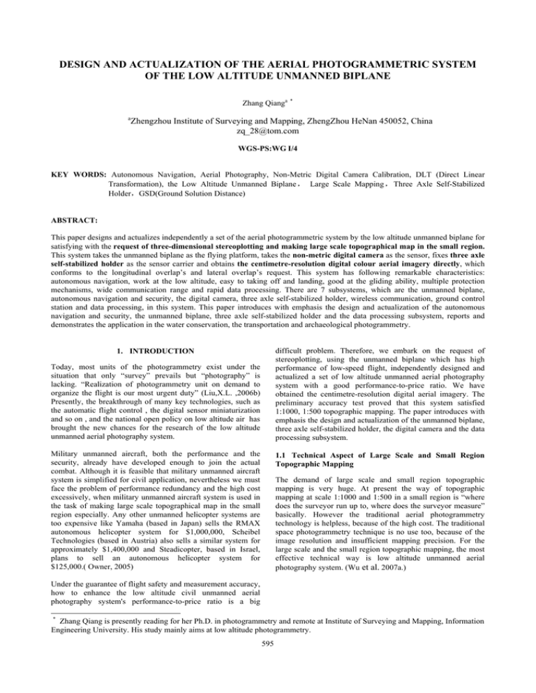
DESIGN AND ACTUALIZATION OF THE AERIAL PHOTOGRAMMETRIC SYSTEM OF THE LOW ALTITUDE UNMANNED BIPLANE Zhang Qianga a * Zhengzhou Institute of Surveying and Mapping, ZhengZhou HeNan 450052, China zq_28@tom.com WGS-PS:WG I/4 KEY WORDS: Autonomous Navigation, Aerial Photography, Non-Metric Digital Camera Calibration, DLT (Direct Linear Transformation), the Low Altitude Unmanned Biplane, Large Scale Mapping, Three Axle Self-Stabilized Holder,GSD(Ground Solution Distance) ABSTRACT: This paper designs and actualizes independently a set of the aerial photogrammetric system by the low altitude unmanned biplane for satisfying with the request of three-dimensional stereoplotting and making large scale topographical map in the small region. This system takes the unmanned biplane as the flying platform, takes the non-metric digital camera as the sensor, fixes three axle self-stabilized holder as the sensor carrier and obtains the centimetre-resolution digital colour aerial imagery directly, which conforms to the longitudinal overlap’s and lateral overlap’s request. This system has following remarkable characteristics: autonomous navigation, work at the low altitude, easy to taking off and landing, good at the gliding ability, multiple protection mechanisms, wide communication range and rapid data processing. There are 7 subsystems, which are the unmanned biplane, autonomous navigation and security, the digital camera, three axle self-stabilized holder, wireless communication, ground control station and data processing, in this system. This paper introduces with emphasis the design and actualization of the autonomous navigation and security, the unmanned biplane, three axle self-stabilized holder and the data processing subsystem, reports and demonstrates the application in the water conservation, the transportation and archaeological photogrammetry. difficult problem. Therefore, we embark on the request of stereoplotting, using the unmanned biplane which has high performance of low-speed flight, independently designed and actualized a set of low altitude unmanned aerial photography system with a good performance-to-price ratio. We have obtained the centimetre-resolution digital aerial imagery. The preliminary accuracy test proved that this system satisfied 1:1000, 1:500 topographic mapping. The paper introduces with emphasis the design and actualization of the unmanned biplane, three axle self-stabilized holder, the digital camera and the data processing subsystem. 1. INTRODUCTION Today, most units of the photogrammetry exist under the situation that only “survey” prevails but “photography” is lacking. “Realization of photogrammetry unit on demand to organize the flight is our most urgent duty” (Liu,X.L. ,2006b) Presently, the breakthrough of many key technologies, such as the automatic flight control , the digital sensor miniaturization and so on , and the national open policy on low altitude air has brought the new chances for the research of the low altitude unmanned aerial photography system. Military unmanned aircraft, both the performance and the security, already have developed enough to join the actual combat. Although it is feasible that military unmanned aircraft system is simplified for civil application, nevertheless we must face the problem of performance redundancy and the high cost excessively, when military unmanned aircraft system is used in the task of making large scale topographical map in the small region especially. Any other unmanned helicopter systems are too expensive like Yamaha (based in Japan) sells the RMAX autonomous helicopter system for $1,000,000, Scheibel Technologies (based in Austria) also sells a similar system for approximately $1,400,000 and Steadicopter, based in Israel, plans to sell an autonomous helicopter system for $125,000.( Owner, 2005) 1.1 Technical Aspect of Large Scale and Small Region Topographic Mapping The demand of large scale and small region topographic mapping is very huge. At present the way of topographic mapping at scale 1:1000 and 1:500 in a small region is “where does the surveyor run up to, where does the surveyor measure” basically. However the traditional aerial photogrammetry technology is helpless, because of the high cost. The traditional space photogrammetry technique is no use too, because of the image resolution and insufficient mapping precision. For the large scale and the small region topographic mapping, the most effective technical way is low altitude unmanned aerial photography system. (Wu et al. 2007a.) Under the guarantee of flight safety and measurement accuracy, how to enhance the low altitude civil unmanned aerial photography system's performance-to-price ratio is a big * Zhang Qiang is presently reading for her Ph.D. in photogrammetry and remote at Institute of Surveying and Mapping, Information Engineering University. His study mainly aims at low altitude photogrammetry. 595 The International Archives of the Photogrammetry, Remote Sensing and Spatial Information Sciences. Vol. XXXVII. Part B1. Beijing 2008 1.2 Current Research of Low Altitude Unmanned Aerial Photography System status of power, control instructions and so on, between the unmanned biplane and the ground control station. The research results of low altitude unmanned aerial photography system attract much attention in recent years. Chen (Chen,H.B et al.2001a) introduced one kind of the aerial photography and remote sensing system based on the miniature model airplane with automatic pilot, which suits to remote sensing general survey for the unpopulated area. It can capture the decimetre-resolution image at definite altitude and fixed point. Sun (Sun,J., et al. 2003a) reported a kind of unmanned airplane named UAVRS-II. This system takes plane array CCD digital camera and the single axle steady holder. It can capture the decimetre-resolution image too and satisfy cartography specifications at scale 1:10000. Yan (Yan, L.et al, 2004a) reported one kind of aerial photography and remote sensing system by an advanced unmanned aircraft which can achieves the performance of the traditional aerial photography craft. It can automatically take off and land with 100kg payload, flight for 30 hours, carry SAR, infrared sensor and visible light CCD digital camera. But as stated by Yan speaks frankly, if this system becomes the sustainable practical remote sensing platform, it must further be enhanced the performance-to-price ratio. In digital camera subsystem, we selected the Canon EOS-1 Ds MarkII non-metric digital camera with EF 17-35mm f/2.8L USM lens, image size: 36mm×24mm, effective pixels: 4992×3328, focal length : 17-35mm, pixel size: 0.0072mm. In ground control station subsystem, we took IFLY40 automatic pilot and adopted GCS300 ground control station software. It is given in Figure 2. The GCS300 includes the real-time monitor module, the flight management module and the track planning module. After receiving the feedback information from the air, the real-time monitor module can display the current status of the biplane's position, the power source, the fuel, the air speed, the ground speed and so on. The flight control module permits the operator to adjust and revises the aerial mission during the flight, simultaneously in the emergency situation, allows the operator to send out the forced landing or the deploying landing parachute instruction to the biplane. The track planning module permits the operator, according to generally combined factors on degree of overlap, safety, flight time, etc, to construct a GPS waypoint grid over a map of the desired location and more than 144 task points per air line. The GPS track coordinates and task points are then downloaded to the flight computer though the UHF radio before taking off. We think that there is a big space to enhance performance-toprice ratio of the fixed wing unmanned aircraft aerial photography system. The concrete technical way is design of it should combine the specialized application. The performance of it should math the demand of professional field. Thus we can avoid wasting the resources. 2. SYSTEM FUNCTION AND STRUCTURE In line with specialized application and low cost, especially we designed one kind of low altitude aerial photogrammetric system in view of large scale and small region topographic mapping. There are 7 subsystems, which are the unmanned biplane, autonomous navigation and security, the digital camera, three axle self-stabilized holder, wireless communication, ground control station and data processing, in this system. Schematic function diagram of the system is given in Figure 1. Air Autonomous Navigation and Security Unmanned Biplane The unmanned biplane, which carries a 108cc gasoline engine and a landing Parachute, is 3.7m long, 1.5m high. Its wingspan is 3.5m, gross weight: 40kg, cruise speed: 40km/h, flying speed: 50~100 km/h, flight Time: 2h, control radius: 20km and flight altitude: 100m~4,000m. The airframe is the light quality timber frame made of Tung and carbon fibre board. The unmanned biplane is shown in Figure 3. Wireless Communication Digital Camera Ground Control Station As follow We will describe with emphasis the design and actualization of the unmanned biplane, the autonomous navigation and security, three axle self-stabilized holder, the digital camera and the data processing subsystem, 2.1 The Unmanned Biplane 3 Axle Self-stabilized Holder Wireless Communication Figure 2. The UI of GCS300 Ground Control Station Software Ground Data Processing Figure 1. Schematic Function Diagram of the System In wireless communication subsystem, we used the UHF digital radio, whose communication distance may reach 20km, to pass on the messages, such as attitudes of the biplane, flight speed, 596 The International Archives of the Photogrammetry, Remote Sensing and Spatial Information Sciences. Vol. XXXVII. Part B1. Beijing 2008 Figure 5. The landing parachute is deployed in the sky 2.3 Three Axle Self-Stabilized Holder Figure 3. The Unmanned Biplane In autonomous navigation mode, the flight computer will control the flight of the unmanned biplane according to the GPS waypoint. When the crosswind is less than 10m/s, the flight computer may control unmanned biplane to flight along air line. The angle of roll and pitch are not bigger than 4° generally. Three axle self-stabilized holder subsystem includes the body made of hard Aluminium alloy, the big torsion high-speed servo motor(36kg/cm,160°/s) made of Titanium alloy,three axle digital compass made by Honeywell and two axle accelerometer made by ADI and the CPU based on kernel ARM7. The Schematic Diagram is given in Figure 6. The CPU uses the data of digital compass and accelerometer to solve current attitude angles (Heading, Pitch and Roll) by Strapdown attitude resolution. After CPU calculates current the angle error of the holder with the horizontal plane and the north, it uses the PID control algorithm to output the PWM signal to drive the servo motor, then the angle errors is corrected automatically and the holder returns to the horizontal plane. On the other hand the CPU always read the GPS position information from the CAN Bus of the IFLY40 automatic pilot. When the flight platform has entered the range of exposure station, the CPU is waiting for the three attitude angles is less than tolerance. If all conditions is satisfied, one picture will be captured. 2.2 Autonomous Navigation and Security The autonomous navigation and security subsystem are made up of the flight computer, the OEM GPS receiver, three axle MEMS gyro, three axle MEMS accelerometer, the barometric pressure altimeter, the barometric air speed meter, the digital magnetic compass, the RC receiver, the servo, manual/automatic(M/A) switch, I/O board and landing parachute. The flight computer, which uses double CPU of ARM7TDMI kernel, undertakes the computation tasks of mission navigation and the flight control. The flight control CPU realizes the attitude control in the stable control's foundation based on the data fusion of the apdown attitude resolution and the bivectorial attitude resolution. Otherwise mission navigation CPU uses feed back PID and the forward feed back control algorithm to ensure normal flight after getting the results calculated by flight control CPU. The schematic diagram of autonomous navigation and Security is given in Figure 4. Self-Stabilized Holder Digital Compass Aaccelerometer Landing Parachute Digital Compass OEM GPS Accelerometer & gyro Flight Computer IO Board Servo M/A Switch Self-stabilized RC Receiver Digital Camera A R M 7 C P U Heading Servo Motor x axis Servo Motor y axis Servo Motor Digital Camera Barometric Altimeter Air Speed Meter Figure 6. The Schematic Diagram of the Self-Stabilized Holder Digital Radio The precision of heading correction is smaller than 1°. The precision of horizontal plane correction may reach 0.5°. The scope of heading correction is ±45°. The scope of horizontal plane correction may reach ±60°. The computation frequency is 50Hz. The angular correction speed may reach 50°/s. Figure 4. The Schematic Diagram of Autonomous Navigation and Security This subsystem has established the perfect security mechanism. When the status of flight platform appears exceptionally, for example, the fuel soon exhausts, the flight attitude beyond the normal range, the flight altitude is excessively low, etc, flight control CPU can judge the degree of emergency automatically, thus It may choose to fly to the takeoff point, fly to the spare landing field or eject the emergency landing parachute directly. The unmanned biplane then floats towards the ground at a slow speed. The landing parachute is deployed in Figure 5. 2.4 Data Processing The data processing subsystem includes the unmanned biplane image special processing module and the photogrammetric general module. The special processing modules consist of three functional modules including the camera calibration, the image distortion error correction, the original image jointing by the free network (the results in Test 2.) The image can be 597 The International Archives of the Photogrammetry, Remote Sensing and Spatial Information Sciences. Vol. XXXVII. Part B1. Beijing 2008 ⎧ Δ x = ( x − x 0 )( k 1 r 2 + k 2 r 4 + k 3 r 6 + L) + p1 [ r 2 + 2( x − x 0 ) 2 ] + (1) ⎪ 2 p 2 ( x − x 0 )( y − y 0 ) + b1 ( x − x 0 ) + b2 ( y − y 0 ) ⎪ ⎨ 2 4 6 2 2 ⎪ Δ y = ( y − y 0 )( k 1 r + k 2 r + k 3 r + L) + p 2 [ r + 2( y − y 0 ) ] + ⎪ 2 p1 ( x − x 0 )( y − y 0 ) + b 1 ( y − y 0 ) + b 2 ( x − x 0 ) ⎩ passed to the photogrammetric general module for the survey and topographic mapping after distortion error correction. 2.4.1 Calibration of Non-Metric Digital Camera: There are two types digital cameras can be use for photogrammetry: metric digital camera and non-metric digital camera. With the rapid development of science and technology, the performance of normal non-metric digital camera is increasingly enhanced, which easy satisfies many photographic conditions with a low cost. But in generally speaking, the elements of interior orientation are unknown and the lens distortion is too bigger for normal non-metric digital camera. These shortcomings badly influence measurement accuracies. Where Recently the research of non-metric digital camera calibration was more and more. In the literature that I have seen(Jiang,D.Z et al, 2001a; Jiang,D.Z., Sun, K. 2001a.; Miao,H.J. et al, 2005a), in the digital camera calibration, which generally is based on outdoor standardization field or indoor standardization field, we can obtain elements of interior orientation and/or the lens distortion by solute the resection equation or direct linear transformation (DLT) equation. When we solute interior orientation parameters and lens distortion parameters simultaneously in three dimension with multi-Images, we find it difficult. In this paper, we has founded the mathematical model of the camera calibration, put forward the adoption of the multiimages iteration method to calculate the coefficients of the DLT and distortion parameters in groups by three-dimensional ground control points (GCP), The precision of camera calibration are confirmed by the experiments of resection and forward intersection, and the satisfactory effect is obtained. In order to confirm the experimental results, we use commercial software Australias, V-STARS and our DLT algorithm to solve interior orientation and the distortion parameter respectively. Table 1 gives the result of calibration and comparison for Canon EOS-1 Ds MarkII non-metric digital camera with EF 1735mm f/2.8L USM lens. Parameter f x0 y0 k1 k2 k3 p1 p2 b1 b2 Australias V-STARS 1.7585E+001 -8.1585E-002 1.4029E-001 3.3676E-004 -8.1695E-007 7.7140E-010 -2.9201E-005 -6.5096E-005 -5.6305E-005 3.2589E-006 1.7584114e+001 -1.17642e-001 1.31335e-001 3.317442e-004 -7.573241e-007 6.321037e-010 -1.861459e-005 -4.495442e-005 -9.446709e-005 9.940657e-005 △x and △y = distortion error of pixel x and y = pixel coordinate x0 and y0 = principal point of photograph coordinate k1, k2, k3… = radial distortion coefficient of the lens distortion p1 and p2 = The tangential distortion coefficient of the lens distortion r = radial length. Figure 7 gives the result comparison of original image and correction image. Figure 7. The Result Comparison of Original Image and Correction Image. 3. APPLICATION AND ACCURACY TESTING This system has already been used successfully in the aerial photography and photogrammetry project such as Xixia water conservancy project, the tomb of Han dynasty archaeological photogrammetry project at Danjiangkou Reservoir, the Guangzhou new passenger station of railway transport of passengers of Wuhan-Guangzhou railway , and so on. 3.1 Test 1. Xixia Water Conservancy Project Improved DLT algorithm 1.7568629e+001 3.7487142e-002 5.04211522e-002 3.3308901e-004 -7.635857e-007 6.325000e-010 -5.604260e-005 -8.063132e-005 -6.479239e-005 7.356245e-005 Xixia water conservancy project is an auxiliary part of the Xiaolangdi water conservancy project of the Yellow River. The project is located in the Xiaolangdi dam site of downstream Yellow River main current, gets down is apart from Zhengzhou 116km. This flight of aerial photography was invited on the Henan Province Surveying and Mapping Department on 2 villages nearby reservoir altogether 1.8km2 areas. The part of images are shown in Figure 8. Table 1. The Result of Calibration (unit: mm) 2.4.2 Distortion Error Correction: After we get interior orientation parameters and lens distortion parameters, we substitute coordinate of original pixel into Eq.1. one by one to solve every pixel correction value. The distortion error of pixel is Figure 8. Xixia Aerial Images 598 The International Archives of the Photogrammetry, Remote Sensing and Spatial Information Sciences. Vol. XXXVII. Part B1. Beijing 2008 Figure 10. One Image of The new railway passenger station of Guangzhou 3.2 Test 2. Archaeological Photogrammetry Project The tomb of Han dynasty archaeological photogrammetry project locates at the end of The Danjiangkou Reservoir where Huangshui River and Dan River’s junction is. The working area is 1km2. According to the request of archaeology tasks, we set two flight altitudes during aerial photography, gains separately two kind of resolution's image, GSD = 5cm and GSD = 10cm. Then we use the way of the free net adjustment to realize 25 original images joining. The mosaic result is shown in Figure 9. 3.3 Test 3. The New Railway Passenger Station of Guangzhou The new railway passenger station of Guangzhou lies between Zhong village and Shibi village in Guangzhou Fanyu District. In this task we took the location of the new railway passenger station as the centre of working area, and expanded 1.5km all around respectively. The total area is 9km2. The area is flat terrain. There are some villages, tree-nurseries, orchards and much cultivated land in the working area. Figure 11. the overview of all images Both orientation points and check points are ground control points. Looking from the forward intersection result, X Maximum error is the 0.10m, Y Maximum error is 0.09m, Z Maximum error is 0.15m. They all satisfy 1:500 mapping specification. 4. CONCLUSION This paper designs and actualizes independently a set of the aerial photogrammetric system by the low altitude unmanned biplane for satisfying with the request of three-dimensional stereoplotting. The results of test of many survey areas indicate that this system flies in security and satisfies the precision of making large scale topographical map in the small region. According to the existing test result, puts forward two proposals to improvement of this system: 1. Using the extra payload, we will integrate synthetic aperture optics camera and further raise the efficiency; 2. Considering the way of taking off and landing, we will improve the adaptive ability of location. Figure 9. The Image of Han dynasty Tomb In this task of the aerial photography, the flight altitude is approximately 118 meters; we have gotten altogether 840 images whose ground resolution is 5cm. All images are clear and vivid. We did not find any aerial photographic gap. Forward lap and side overlap are 100% good. The biggest image slope angle is less than 2° and the biggest image swing angle is less than 5°. The skew coefficient of aerial line is less than 1%. The biggest flight altitude difference is 3m. One of all images is shown in Figure 10. and the overview of all images is shown in Figure 11. ACKNOWLEDGMENT. Financial supports from Institute of Surveying and Mapping, Information Engineering University are highly appreciated. REFERENCES Liu,X.L. 2006b, Academic report. Institute of Surveying and Mapping, Information Engineering University. Owner, 2005.AutoCopter Product Briefing. http://www.neuralrobotics.com/.(accessed 28 Apr. 2005) Wu,Y.D.,Zhang,Q.,Wang,H.,Guo,J.H. 2007a.Technique of Low Aerial Photography and Photogrammetry System by Unmanned Helicopter.Journal of Zhengzhou Institute of Surveying and Mapping,24(5),328-331. Chen,H.B., Ma, S.Q., Wang,A.G., Xuan, Y.J.,Pan,A.Y., L i,Q., Fan. K.,P., Wang, P.C., Lu, D.R. 2001a. Remote Sensing Systems on Board Autonomous Miniature Aircraf t. Remote Sensing Technology and Application, 16(3), 144-147. 599 The International Archives of the Photogrammetry, Remote Sensing and Spatial Information Sciences. Vol. XXXVII. Part B1. Beijing 2008 Yan, L. ,Lu, S.Q.,Zhao,H.Y.,Zhang,X.H.,Yang,S.W.,Zhao, J.C. 2004a. “Research on key techniques of aerial remote sensing system for unmanned aerial vehicles”, Engineering Journal of Wuhan University., 37(6), 67-70. Jiang,D.Z., Sun,J.l. 2001a. Research on Solving Nonlinear Distortion of Camera Lens. Journal of Southeast University.2001.7(31)4:111-116 Jiang,D.Z., Sun, K. 2001a. Research on Digital Camera Calibration Method.Journal of Nanjing University of Aeronautics& Astronautic.2001-2,(33)1:55-58 Miao,H.J., Zhao,W.J., Liu,X.L. 2005a.Discussions on the Issues in Calibration of Digital Cameras and Photogrammetry. Journal of Capital Normal University(Natural Science dition).20053,(36)1:117-120. Sun,J.,Lin,Z.J.,Cui,H.X.2003a .Research On UAV Remote Sensing System. Remote sensing Information.2003,(1):49-51. 600
