EE-47 Engineer To Engineer Note
advertisement
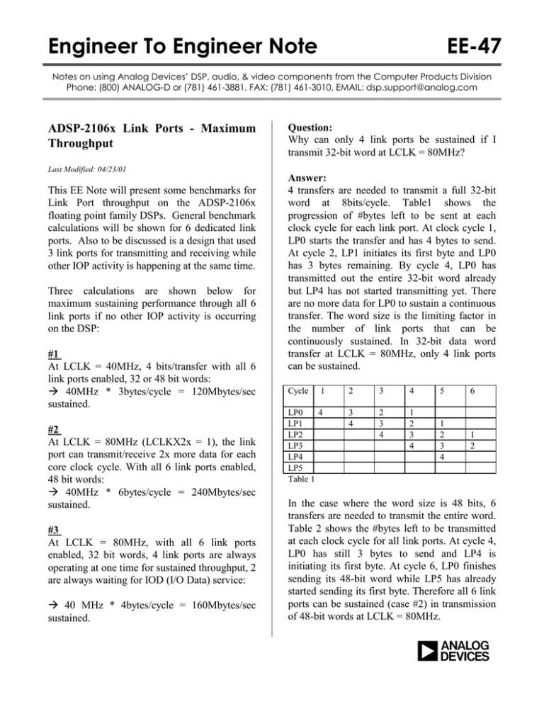
Engineer To Engineer Note EE-47 Notes on using Analog Devices’ DSP, audio, & video components from the Computer Products Division Phone: (800) ANALOG-D or (781) 461-3881, FAX: (781) 461-3010, EMAIL: dsp.support@analog.com ADSP-2106x Link Ports - Maximum Throughput Last Modified: 04/23/01 This EE Note will present some benchmarks for Link Port throughput on the ADSP-2106x floating point family DSPs. General benchmark calculations will be shown for 6 dedicated link ports. Also to be discussed is a design that used 3 link ports for transmitting and receiving while other IOP activity is happening at the same time. Three calculations are shown below for maximum sustaining performance through all 6 link ports if no other IOP activity is occurring on the DSP: #1 At LCLK = 40MHz, 4 bits/transfer with all 6 link ports enabled, 32 or 48 bit words: Æ 40MHz * 3bytes/cycle = 120Mbytes/sec sustained. #2 At LCLK = 80MHz (LCLKX2x = 1), the link port can transmit/receive 2x more data for each core clock cycle. With all 6 link ports enabled, 48 bit words: Æ 40MHz * 6bytes/cycle = 240Mbytes/sec sustained. #3 At LCLK = 80MHz, with all 6 link ports enabled, 32 bit words, 4 link ports are always operating at one time for sustained throughput, 2 are always waiting for IOD (I/O Data) service: Æ 40 MHz * 4bytes/cycle = 160Mbytes/sec sustained. Question: Why can only 4 link ports be sustained if I transmit 32-bit word at LCLK = 80MHz? Answer: 4 transfers are needed to transmit a full 32-bit word at 8bits/cycle. Table1 shows the progression of #bytes left to be sent at each clock cycle for each link port. At clock cycle 1, LP0 starts the transfer and has 4 bytes to send. At cycle 2, LP1 initiates its first byte and LP0 has 3 bytes remaining. By cycle 4, LP0 has transmitted out the entire 32-bit word already but LP4 has not started transmitting yet. There are no more data for LP0 to sustain a continuous transfer. The word size is the limiting factor in the number of link ports that can be continuously sustained. In 32-bit data word transfer at LCLK = 80MHz, only 4 link ports can be sustained. Cycle 1 2 3 4 LP0 4 LP1 LP2 LP3 LP4 LP5 Table 1 3 4 2 3 4 1 2 3 4 5 6 1 2 3 4 1 2 In the case where the word size is 48 bits, 6 transfers are needed to transmit the entire word. Table 2 shows the #bytes left to be transmitted at each clock cycle for all link ports. At cycle 4, LP0 has still 3 bytes to send and LP4 is initiating its first byte. At cycle 6, LP0 finishes sending its 48-bit word while LP5 has already started sending its first byte. Therefore all 6 link ports can be sustained (case #2) in transmission of 48-bit words at LCLK = 80MHz. a Cycle 1 2 3 4 5 6 LP0 6 LP1 LP2 LP3 LP4 LP5 Table 2 5 6 4 5 6 3 4 5 6 2 3 4 5 1 2 3 4 6 5 6 ----------------------------------------------------------As another example, let’s look at a six SHARCs system that is to be designed. Five of the SHARCs will be number crunchers, connected together with the External Port for 32 bits transfers. The last SHARC will act as a dedicated I/O processor, where 3 of its link ports are connected up as inputs, while the other 3 are outputs. The I/O SHARC will then be connected up with the other SHARCs on the external bus. It then will use a broadcast write function to write to the other 5 processors on the board. The I/O SHARC will not have any other tasks. Question: What will be the practical maximum throughput through the link ports if data comes in 1K blocks at any of the link ports in a random fashion? Answer: The key thing is that the DMA IOP bus can sustain a one word per cycle transfer with the RAM (independent of any core accesses). If chaining is used, after each DMA completes 8 words (for links ports) must be transferred over the IOP bus to reinitialize the DMA channel. These 8 words will share the IOP bus bandwidth with the Link DMAs and must be subtracted out of the Max Link bandwidth. Assume: • 25ns, 40MHz CLKIN rate • 32-bit data words sent over Links EE-47 • • • • • 2x Link Clock mode, gives 40Mbytes/s per link or 10Mwords/s per link Max IOP bus (DMA) bandwidth with on-chip RAM is 1 word/cycle DMA chaining is used to auto initialize new DMA block transfers Each Link port DMA chain takes 8 cycles of IOP bus overhead to restart a Link port 1024 words blocks are DMAed over the links Æ Max IOP bus bandwidth = 40Mwords/s Æ #Link ports that can be sustained = (40Mw/s) / (10Mw/s) = 4 Link ports Therefore, the IOP bus is the bottleneck (for 32bit words link transfers) Æ #IOP bus transfers = (1024 cycles/block) + (8 cycles chain overhead/block) = 1032 cycles/block Æ #Words transferred = (1024 cycles/block) Æ Overhead for chaining = 1024/1032 Æ Overall Link port transfer rate is (1024/1032) * 40Mwords/s = 39.68992248062 Mwords/s If DMA chaining is not used and the core needs to reinitialize the Link port transfers then there will be some amount of overhead for interrupt routines, setup of new DMA pointers, and enabling of the transfer. Similar calculations can be applied to the ADSP-2116x to find the maximum throughput. Note: There is an anomaly with the revision 2.0 ADSP-21062 link ports. Basically link Buffer 3 can only be used to transmit and not receive. Remember that there are 6 link buffers and 6 link ports. Any buffer can be logically assigned to any link port so link buffer 3 can be assigned to a link port that is only transmitting. Not all Page 2 Notes on using Analog Devices’ DSP, audio, & video components from the Computer Products Division Phone: (800) ANALOG-D or (781) 461-3881, FAX: (781) 461-3010, EMAIL: dsp.support@analog.com rev 2.0 parts will exhibit this problem but due to the characteristics of the problem we cannot test and reliably screen out problem parts. Please refer to the latest ADSP-21062 anomaly list that describes this problem. EE-47 Page 3 Notes on using Analog Devices’ DSP, audio, & video components from the Computer Products Division Phone: (800) ANALOG-D or (781) 461-3881, FAX: (781) 461-3010, EMAIL: dsp.support@analog.com
